





— Blogs —
—Products—
 Consumer hotline +8618073152920
WhatsApp:+8615367865107
Address:Room 102, District D, Houhu Industrial Park, Yuelu District, Changsha City, Hunan Province, China
Product knowledge
Time:2024-02-20 15:28:19 Popularity:5642
Automatic drip irrigation using soil moisture sensors combines root-zone moisture measurements with an irrigation controller to determine when water should be delivered through drip emitters. Instead of relying only on fixed watering intervals, the system uses measured soil conditions to support irrigation decisions.
A typical soil-moisture-based drip irrigation system includes one or more soil moisture sensors, a controller or PLC, solenoid valves, drip irrigation pipes, a suitable water supply and, where necessary, a pump. Data acquisition and communication equipment may also be added for remote monitoring.
The soil moisture sensor measures water content, while the irrigation controller decides when to operate the valves or pump. These are separate functions. The controller must be correctly configured to interpret the sensor readings and operate the hydraulic equipment safely.
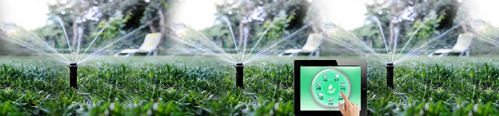
An automatic drip irrigation system uses a controller to manage water delivery through a network of pipes, valves and drip emitters. Soil moisture measurements can be used to enable, delay, start or stop irrigation according to the selected control strategy.
The basic operation follows this sequence:
Soil Moisture Sensor → Irrigation Controller → Valve / Pump Control → Drip Lines → Crop Root Zone
The sensing and control process can be divided into five stages.
The soil moisture sensor is installed at a selected depth and location related to the crop roots and drip irrigation wetting pattern.
Many electronic agricultural sensors estimate volumetric water content (VWC) using dielectric measurement technologies such as FDR or TDR. The result indicates the water content of the localized soil volume surrounding the sensing element.
The measurement should be interpreted according to soil characteristics, sensor calibration and installation conditions.
A compatible sensor sends readings to the irrigation controller, PLC or data acquisition device using its supported output interface.
For example, an RS485 Modbus RTU sensor can be connected to a controller that supports the correct electrical interface, communication parameters and register map.
The receiving device must interpret the measurement units and scaling factors correctly before using the data for irrigation decisions.
The controller compares the measured moisture with configured thresholds or scheduling rules.
Depending on the system, it may permit a scheduled irrigation event, initiate an on-demand watering cycle or delay watering while soil conditions remain sufficiently wet.
Before starting irrigation, the controller may also check water availability, operating permissions, system alarms and other relevant inputs.
When the configured conditions permit irrigation, the controller activates the appropriate valve driver, relay or pump-control interface.
Water then flows through the irrigation pipes and drip emitters into the cultivated soil.
A pump may be required where the water supply does not provide sufficient pressure. Other installations may use an existing pressurized supply or a suitably designed gravity-fed arrangement.
The controller ends irrigation when the applicable stop condition is reached. This may be a moisture threshold, maximum watering duration, delivered volume or another configured control condition.
After watering, soil moisture may continue changing as water moves through the soil. A suitable observation or redistribution period can help prevent unnecessary repeated irrigation commands.
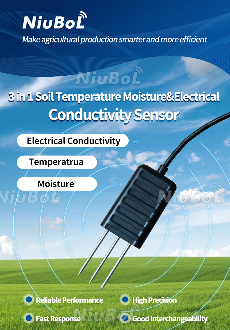
An automatic drip irrigation system requires measurement, control and water delivery components. The configuration should match the intended crop, number of irrigation zones and available water supply.
| Component | Function |
|---|---|
| Soil Moisture Sensor | Measures water content at the selected root-zone location. |
| Irrigation Controller / PLC | Processes measurements and manages irrigation rules. |
| Solenoid Valve | Opens or closes the water supply to an irrigation zone. |
| Pump / Pump Controller | Provides or regulates water delivery where pumping is required. |
| Filter and Pressure Regulation | Supports suitable water delivery conditions for the drip system. |
| Drip Pipes and Emitters | Distribute irrigation water to the intended crop area. |
| Power Supply | Supplies compatible power to sensors, controllers and actuators. |
| Optional Flow / Pressure Sensors | Provide feedback about actual water delivery and hydraulic conditions. |
| Optional IoT Gateway | Transmits monitoring data to a remote platform or server. |
Many irrigation systems use 24 VAC solenoid valves, while other valve and actuator types require different supply voltages. The controller output and electrical switching equipment must be compatible with the selected components.
A soil moisture sensor with RS485 output does not automatically provide a relay output capable of directly operating an irrigation valve or pump.
Soil moisture can be used in irrigation control in more than one way. Two common approaches are scheduled irrigation with moisture-based bypass and on-demand irrigation.
In this method, the irrigation system follows an existing watering schedule. Before each scheduled event, the controller evaluates the soil moisture reading.
If moisture is above the configured threshold, the system may skip that watering event. If moisture is below the threshold, irrigation is permitted to proceed according to the defined schedule.
This approach can be suitable when a farm already has a timer-based drip system and wants to include soil moisture feedback without replacing the entire scheduling strategy.
In an on-demand system, the controller can start irrigation when the measured soil moisture falls below a defined lower threshold, subject to other operating and safety conditions.
Irrigation can stop when an upper moisture threshold or another valid stop condition is reached.
The controller should also account for the time required for irrigation water to reach the sensing location. Without suitable timing rules, a system may continue watering longer than intended or switch repeatedly between operating states.
| Control Method | Start Condition | Stop Condition |
|---|---|---|
| Scheduled with Bypass | Scheduled time and soil moisture conditions permit watering. | Scheduled cycle ends or another controller stop condition occurs. |
| On-Demand | Moisture falls below the configured lower threshold. | Upper threshold, watering limit or another configured stop condition is reached. |
Neither strategy provides a universal irrigation threshold. Suitable values depend on soil water-retention properties, crop requirements, sensor calibration and the irrigation system design.
A threshold is a measurement value used by a controller to make an irrigation decision. In systems using volumetric water content, the threshold is typically expressed as a percentage of soil volume occupied by water.
The same VWC percentage does not indicate identical water availability in every soil. A sandy soil and a clay-rich soil can have different water-retention characteristics, even when their moisture readings are numerically equal.
A lower threshold may be used to identify when the monitored soil zone has become sufficiently dry to consider irrigation.
An upper threshold may be used to stop irrigation after the measured water content has increased to the defined target condition.
Using different start and stop thresholds creates a control band, commonly called hysteresis. This helps reduce repeated rapid switching when readings fluctuate close to one threshold.
| Observed Condition | Possible Controller Response |
|---|---|
| Soil moisture below lower threshold | Start irrigation if operating and safety conditions allow. |
| Soil moisture between thresholds | Maintain the appropriate state according to hysteresis logic. |
| Upper moisture threshold reached | Stop irrigation. |
| Maximum watering duration reached | Stop irrigation and apply the configured limit or alarm. |
| Sensor data missing or invalid | Apply the defined fault response; do not assume the soil is dry. |
| Low source-water level or hydraulic fault | Prevent or stop equipment operation according to the safety design. |
This is an example of control logic, not a fixed NiuBoL controller program. The actual functions must be implemented and verified in the selected irrigation controller or PLC.
In drip irrigation, water is delivered at localized points rather than uniformly across the soil surface. The soil moisture sensor may not respond immediately when the irrigation valve opens.
Water must first move from the emitter toward the sensor's sensing region. The response time depends on soil hydraulic properties, emitter discharge, probe depth and the distance between the sensor and the emitter.
After the valve closes, water may continue moving through the soil. Therefore, the sensor reading can continue increasing even though irrigation has stopped.
For some installations, a controller can use a pulse-and-soak strategy. It applies water for a defined period, pauses irrigation, allows redistribution and then reevaluates the moisture measurement.
The appropriate waiting period must be determined for the actual soil and irrigation conditions. It should not be assumed that every soil reaches its target moisture immediately after water delivery.
Sensor placement is particularly important in drip irrigation because water is applied locally around drip emitters.
A soil moisture sensor should be installed at a representative location within the monitored crop root zone. Its position should consider emitter spacing, soil wetting patterns and the depth of active roots.
A sensor positioned immediately beside the drip emitter may register very wet soil while other parts of the root zone remain drier.
A sensor placed outside the expected wetting pattern may remain relatively dry even when the applied irrigation volume is appropriate for the crop.
The appropriate distance depends on emitter arrangement, soil texture, crop root distribution and the objective of the monitoring system.
A shallow sensor can respond to changes in the upper part of the root zone, while a deeper sensor can provide information about water movement farther into the soil profile.
For crops with deeper roots, monitoring more than one depth may be useful. The required depths should be based on crop conditions rather than applying one fixed installation depth to every farm.
The sensor must maintain suitable contact with the surrounding soil. Air gaps, stones, loose backfill and damaged sensing elements can affect the measurement.
Follow the selected sensor's installation instructions. Avoid locations that are unusually wet, dry or disturbed unless those conditions are intentionally being monitored.
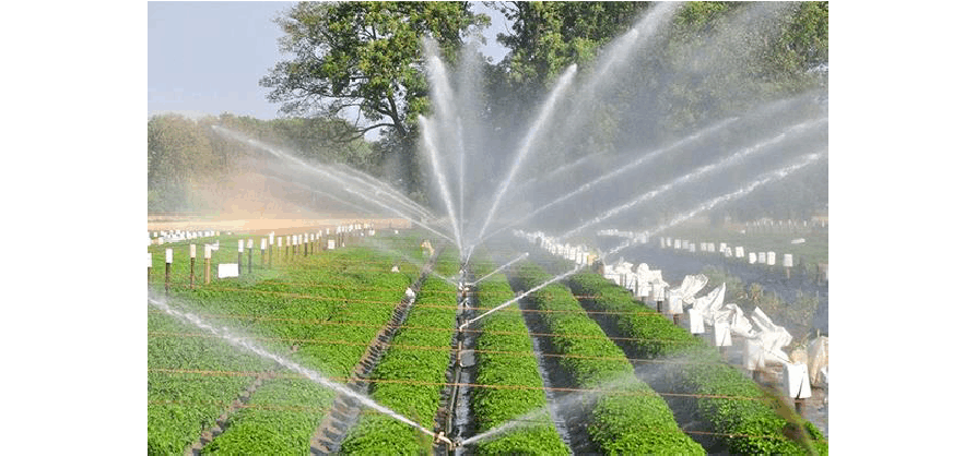
NiuBoL soil moisture sensors with RS485 Modbus RTU outputs can be integrated with compatible PLCs, irrigation controllers, RTUs or data acquisition devices.
A typical wired connection arrangement is:
RS485 Soil Sensor → PLC / Irrigation Controller → Relay / Valve Driver → Drip Irrigation Valve
The controller must correctly read the sensor's Modbus address and measurement registers. The output device must have the appropriate electrical capacity and protection for the connected actuator.
An RS485 communication connection does not supply power to a valve or automatically provide a pump-start output.
Multiple compatible Modbus RTU sensors may share an appropriately designed RS485 bus, provided they use unique device addresses and compatible communication settings.
For multiple irrigation zones, the controller must associate the correct measurement points with the valves or watering areas they represent.
The number of sensors does not automatically determine the number of irrigation zones. One zone may require several measurement depths or locations, while the hydraulic system may contain separate zones with their own valve controls.
A compatible IoT gateway can transmit soil moisture readings and available operating information to a remote monitoring platform.
Network connectivity may use Ethernet, Wi-Fi, cellular communication or a suitable wireless sensor node, depending on the selected equipment.
Remote monitoring is different from automatic irrigation control. The presence of a gateway or cloud platform does not guarantee that it can directly operate valves or pumps without the required controller functions.
For additional information, see IoT Soil Moisture Sensor: Working Principle and Connectivity.
Soil moisture data describes water conditions around the installed probe. It does not independently verify the hydraulic operation of the irrigation system.
Additional measurements may be useful when the irrigation project requires reliable pump, valve and water delivery monitoring.
| Measurement | Purpose |
|---|---|
| Soil Moisture | Observes the water content at the monitored root-zone location. |
| Water Flow | Measures water delivery through a pipeline or irrigation zone. |
| Water Pressure | Monitors hydraulic conditions in pumps, filters and irrigation lines. |
| Water Level | Provides information about the available water supply in a tank or reservoir. |
| Rainfall | Provides precipitation information that may be considered when scheduling irrigation. |
A valve-opening command does not prove that water has reached the crop. For example, a closed upstream valve, blocked filter or pump problem may prevent the intended water delivery.
Flow and pressure measurements can provide useful hydraulic feedback when integrated into a suitable monitoring and alarm system.
Automatic irrigation systems should be designed to handle sensor errors, hydraulic problems and unexpected operating conditions.
| Problem | Practical Check or Protection |
|---|---|
| Sensor Does Not Respond After Watering | Check emitter position, wetting pattern, sensing depth and soil contact. |
| Repeated Valve Switching | Use suitable hysteresis, timing rules and irrigation intervals. |
| Irrigation Continues Too Long | Configure a maximum watering duration and appropriate stop conditions. |
| No Water Delivery | Check water source, valve status, pump operation and optional flow/pressure readings. |
| Invalid or Missing Sensor Data | Check sensor power, communication and the controller's fault response. |
| Unexpectedly High Water Consumption | Inspect leakage, valve operation, watering duration and flow records. |
| Loss of Internet Connection | Determine whether permitted irrigation control can continue locally and how alarms/data are handled. |
The correct fault response depends on the crop, water source, hydraulic design and consequences of equipment failure. For unattended installations, local control and clearly defined safe operating states should be considered.
Soil-moisture-guided drip irrigation can be applied to various growing environments. The control system and sensor arrangement should be selected according to the crop and irrigation configuration.
Greenhouses: Separate moisture measurements can support monitoring of cultivation zones with different plants, substrates or irrigation schedules.
Orchards and Vineyards: Root-zone monitoring can provide information about irrigation response at selected locations and depths.
Vegetable Cultivation: Soil moisture measurements can be included in irrigation scheduling where regular watering and localized drip application are used.
Nurseries and Landscaping: Moisture-based control can help evaluate whether scheduled irrigation is necessary under the monitored soil conditions.
The suitability of a soil moisture sensor depends on the growing medium. A sensor calibrated for mineral soil should not automatically be assumed to provide equivalent performance in every artificial substrate.
A properly configured soil-moisture-based irrigation system can provide more information about root-zone water conditions and help reduce unnecessary irrigation events compared with an unsuitable fixed schedule.
Automated control can also reduce the need for manual valve operation and support more consistent implementation of defined irrigation rules.
However, installing soil moisture sensors does not automatically guarantee a particular amount of water savings, higher crop yields, reduced energy costs or fewer plant diseases.
Actual outcomes depend on the soil, crop, sensor placement, irrigation uniformity, controller configuration, water supply and management practices.
A reliable system should therefore be evaluated by both the quality of the measurements and the actual performance of its irrigation equipment.
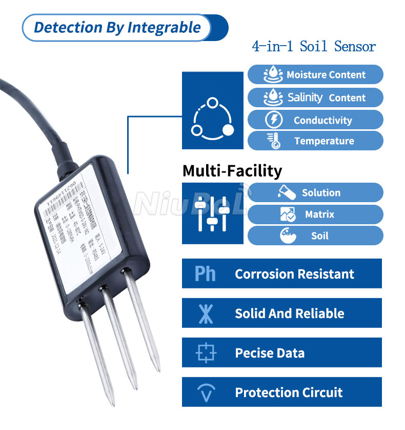
A1. The sensor measures soil moisture and sends data to a compatible controller. The controller evaluates the configured irrigation conditions and operates the appropriate valve or pump-control equipment.
A2. A standard RS485 measurement sensor normally supplies data rather than actuator power or switching control. A suitable controller and compatible valve driver or relay are required.
A3. There is no universal percentage. Suitable thresholds depend on soil texture, water-retention characteristics, crop requirements, root depth and sensor calibration.
A4. Water continues redistributing through the soil after irrigation stops. The reading may increase when the wetting front reaches the sensing region or additional moisture moves through the monitored layer.
A5. Yes. A compatible multi-zone controller can use readings from separately identified soil sensors and apply control rules to the associated irrigation zones. Appropriate wiring, device addressing and control outputs are required.
A6. Not necessarily. A suitable local controller can perform automatic irrigation without Internet access. Internet connectivity is needed only for functions such as remote monitoring, remote commands or external platform integration.
A7. The controller can be designed with appropriate fault handling, maximum watering duration, operating permissions and optional hydraulic feedback. The exact protections depend on the system design and must be configured and tested.
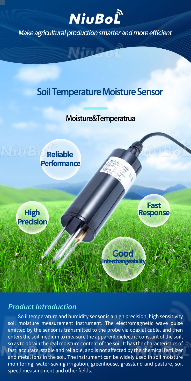
NiuBoL provides soil moisture and temperature sensors suitable for agricultural monitoring and integration with compatible irrigation controllers, PLCs and data acquisition systems.
The NBL-S-THR Soil Temperature and Moisture Sensor provides root-zone moisture and temperature measurements. For additional soil parameters, the NBL-S-TMC Soil Temperature, Moisture and EC Sensor can be considered.
For projects requiring flow, pressure, water level and weather measurements in addition to soil moisture, see Sensors for Irrigation Systems.
For sensor selection, specify the soil type, crop, drip emitter arrangement, number of irrigation zones, measurement depths, output interface, power supply, controller or PLC model and data acquisition requirements.
The sensor provides measurement data; irrigation control equipment and actuators must be selected and configured separately according to the project requirements.
Prev:Soil Moisture Sensor vs Tensiometer: Key Differences
Next:What is the difference between humidity sensor and moisture sensor?
Related recommendations
Sensors & Weather Stations Catalog
 Agriculture Sensors and Weather Stations Catalog-NiuBoL.pdf
Weather Stations Catalog-NiuBoL.pdf
Agriculture Sensors Catalog-NiuBoL.pdf
Water Quality Sensor Catalog-NiuBoL.pdf
Related products
 Combined air temperature and relative humidity sensor
 TDR Soil Moisture & Temperature Sensor for irrigation| RS485 |4-20mA| NBL-S-THR
 Soil pH sensor RS485 soil Testing instrument soil ph meter for agriculture |NBL-S-PH
 Wind Speed sensor Output Modbus/RS485/Analog/0-5V/4-20mA
 Tipping bucket rain gauge for weather monitoring auto rainfall sensor RS485/Outdoor/stainless steel
 Pyranometer Solar Radiation Sensor 4-20mA/RS485


Screenshot, WhatsApp to identify the QR code
WhatsApp number:+8615367865107
(Click on WhatsApp to copy and add friends)

