





— Blogs —
—Products—
 Consumer hotline +8618073152920
WhatsApp:+8615367865107
Address:Room 102, District D, Houhu Industrial Park, Yuelu District, Changsha City, Hunan Province, China
Product knowledge
Time:2025-11-27 14:36:10 Popularity:939
Quick answer: A rainfall weather station combines a rain gauge, data logger, power supply and communications. For project selection, confirm the precipitation type, required resolution, output interface, site exposure, freezing conditions and maintenance access before comparing models.
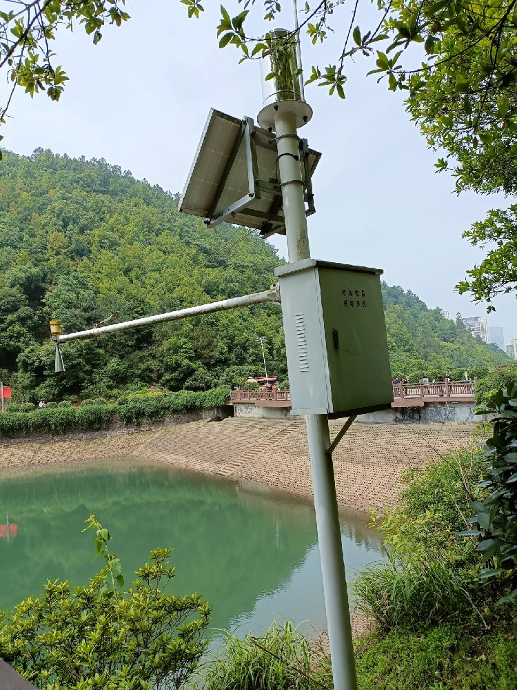
A rainfall weather station records precipitation at an identified location and makes the observations available to a receiving system. The gauge is only the measuring component. Its output still needs counting or decoding, timestamps, power where required and an agreed treatment of interruptions. A communications cabinet beside a gauge is not enough if the records cannot distinguish a dry interval from a failed instrument.
The term rain sensor also describes devices that detect wetness or the presence of rain. A contact that closes when a surface becomes wet can support a local rain interlock, but that signal does not establish millimeters of accumulated rainfall. Put the required quantity on the equipment schedule: rain presence, rainfall depth, interval intensity or a broader set of weather observations.
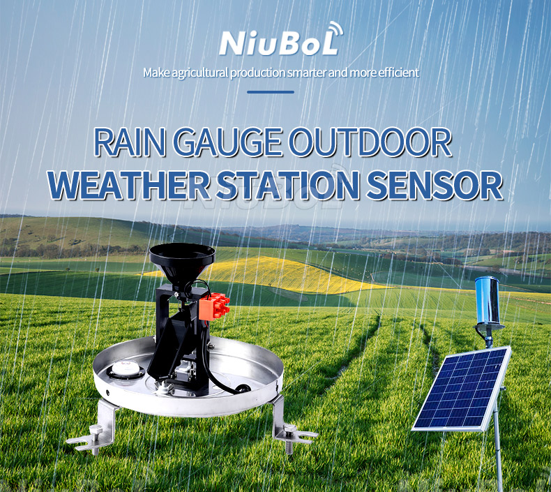
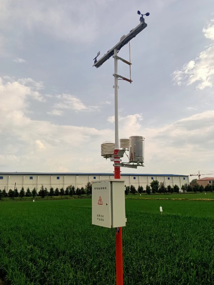
An existing PLC or RTU with a suitable counter may need only a pulse gauge and its mounting arrangement. A remote drainage point without acquisition or site power needs a logger, enclosure, energy supply and communications as well. A farm combining rainfall with wind and air observations needs a station architecture that preserves the identity and timing of each measurement.
Specify the observation period before choosing the transmission interval. An irrigation rainfall station may use accumulated depth to review a watering plan, while drainage rainfall monitoring may need shorter event records. Neither requirement means the gauge alone can calculate catchment runoff, soil infiltration or a pump operating decision. Those need additional observations and project logic.
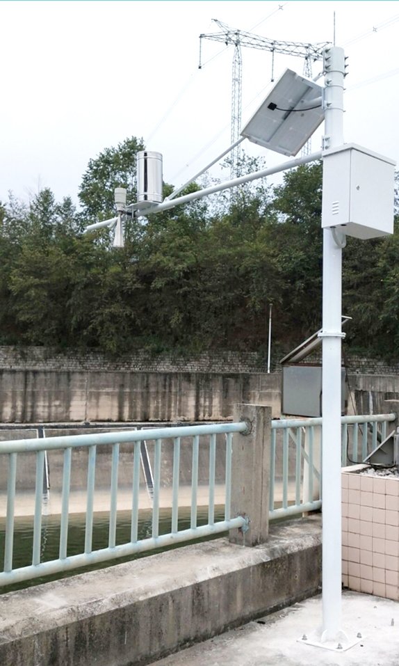
A tipping-bucket rain gauge collects water through a known opening. When one bucket reaches its calibrated volume, it tips and produces a pulse. A logger counts the pulses to calculate accumulated rainfall and uses their timing to estimate rainfall intensity. The station does not measure snowfall correctly unless the instrument and installation include an appropriate heating or precipitation method.
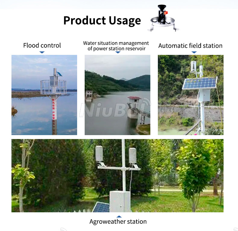
The NBL-W-RS is used as the precipitation input in weather, hydrology, irrigation and drainage-monitoring systems. Pulse, analog and RS485 variants serve different logger and controller architectures; the exact option must be confirmed on the quotation and wiring document.
For a 0.2 mm-per-tip instrument, one tip in a five-minute interval gives an interval average of 2.4 mm/h: 0.2 x 60/5. Two tips give 4.8 mm/h. This is a calculation example, not proof that rain fell at a steady rate throughout either interval. A finer display cannot recover water that has not yet completed a bucket tip.
Rainfall intensity reporting should therefore identify whether it uses fixed-interval accumulation, time between tips or another defined algorithm. Near the start and end of light rain, residual water in the bucket affects the apparent event boundary. Compare gauges using the same accumulation period and reporting method rather than the number of decimal places shown on a dashboard.
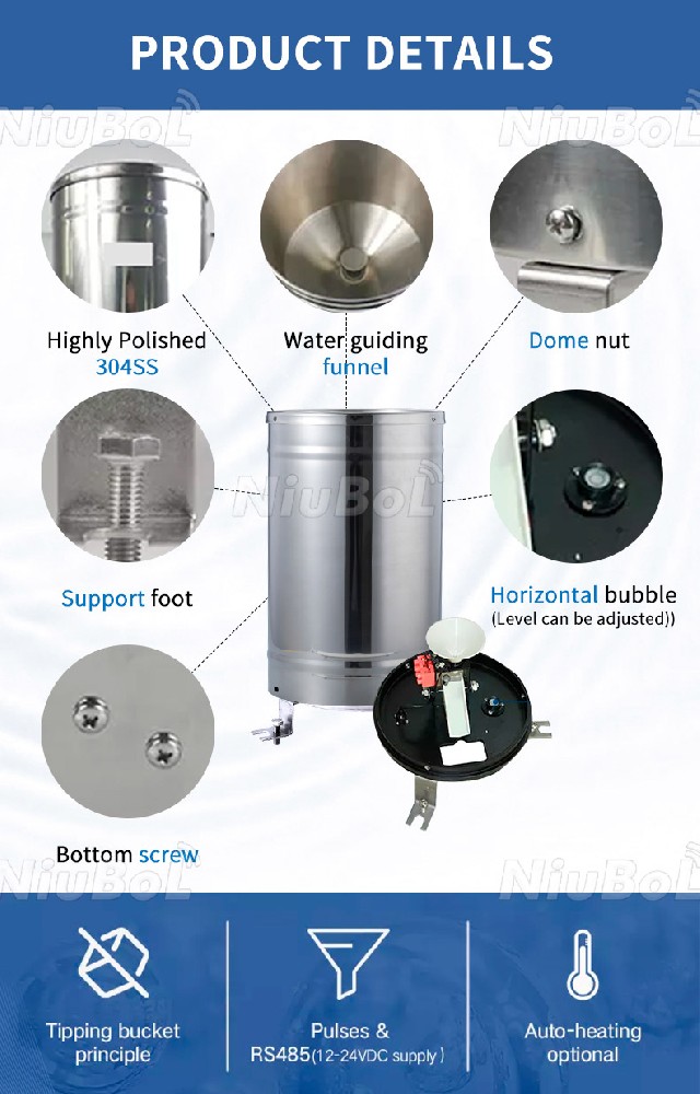
The NiuBoL NBL-W-RS tipping-bucket configuration below measures liquid precipitation. Its collector, mechanical resolution and test conditions belong to that configuration; they should not be copied to every gauge with a similar housing. Select the ordered electrical version separately.
| Item | NBL-W-RS configuration | Selection consequence |
|---|---|---|
| Collector diameter | 200 +/-0.6 mm | Keep the collection opening level and unobstructed |
| Intensity range | 0-4 mm/min | Check the design rainfall intensity, not only the annual total |
| Resolution | 0.2 mm per tip, approximately 6.28 mL | Use the correct pulse factor in the receiver |
| Accuracy | +/-4% under the specified indoor static test at 2 mm/min | Not a guarantee of whole-site field uncertainty |
| Output options | Reed-switch contact; selected 0-2.5 V, 0-5 V or RS485 version | Match the delivered electronics to the input type |
| Supply options | DC 5 V or DC 12-24 V, by configuration | Do not infer supply requirements from the collector shape |
| RS485 communication | Modbus RTU; 9600 bps default for this configuration | Check framing, register scaling and permissible polling interval |
| Operating temperature | 0-50 degrees C | Freezing exposure needs a different precipitation arrangement |
| Cable | 5 m standard | Specify jacket and extension protection for the actual route |
| Power demand and ingress rating | Require the selected electrical assembly's values | Do not assign a whole-station rating to a mechanical collector |
A pulse rain gauge input must accept the actual contact behavior and retain counts at the expected tip rate. Check minimum accepted pulse width, contact bounce treatment and what happens while the logger is busy or restarting. Excessive filtering can discard real tips; inadequate filtering can count a single operation more than once.
For a powered voltage version, confirm the relationship between voltage and the reported quantity. A 0-5 V input alone does not say whether the signal represents an accumulated value or another configured output. The receiver must use the delivered scale and reset behavior. Do not connect a voltage output to a dry-contact input simply because both devices use two convenient terminals.

With RS485 Modbus RTU, identify the rainfall register, scale, counter behavior and reset command before coding the PLC or data logger. Check whether a restart clears the instrument value, retains it or requires a new baseline. A zero after power restoration must not be interpreted automatically as negative rainfall or a fresh dry observation.
The receiver should separate an instrument total from the accumulated total it publishes for an event or calendar period. Define the reporting time zone and retain enough information to recalculate a daily value when packets arrive late. Query failures should create an invalid or missing state, not a series of synthetic zeros. Test the actual firmware behavior rather than assuming every Modbus gauge has the same counter.
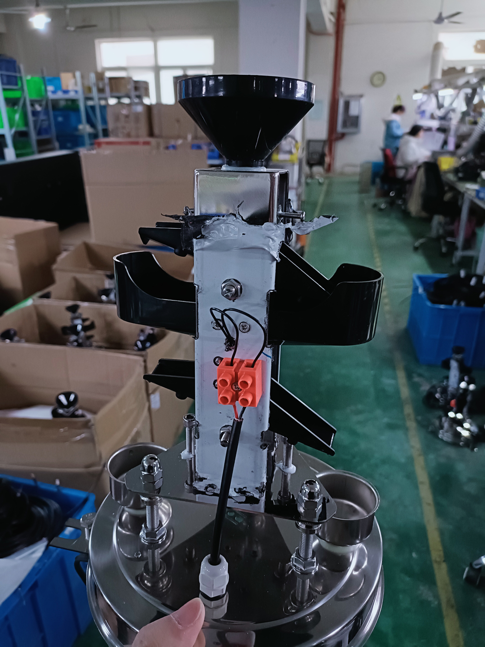
The NBL-W-DRS double tipping-bucket rain sensor is a separate option with 0.1 mm resolution and a specified 0-4 mm/min intensity range. Its smaller increment can be useful where the reporting task needs finer accumulated steps. It does not make the complete station twice as accurate.
Compare the calibration arrangement, usable intensity range, output, mounting access and service procedure alongside resolution. The internal collection and metering arrangement differs from a basic tipping mechanism. A photograph of the internal buckets cannot establish the pulse factor of every delivered variant. Put the model and increment together on the purchase order and logger configuration sheet.
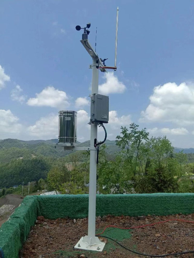
Choose an open, representative site away from splash surfaces and airflow disturbances. Level the collector using its leveling arrangement and the applicable installation tolerance. Confirm that the bucket moves freely, the drain path is clear and the cable entry is weather protected. Use a controlled-water test to verify the collector and a separate record check to verify scaling and timestamps.
A hydrological rainfall network may use a separate low-mounted collector even where the communications antenna or wind instruments need a taller mast. Check nearby trees, roof edges, fences and new structures that may affect catch or splash. A location with a strong radio signal is not necessarily a representative precipitation location.
Provide safe access to inspect the filter, tipping assembly and level after storms. Also consider the drain outlet: retained water, insects or an obstruction can change the mechanism's behavior. Record any relocation or change in exposure so a shift in the rainfall series is not mistaken for a climatic change.
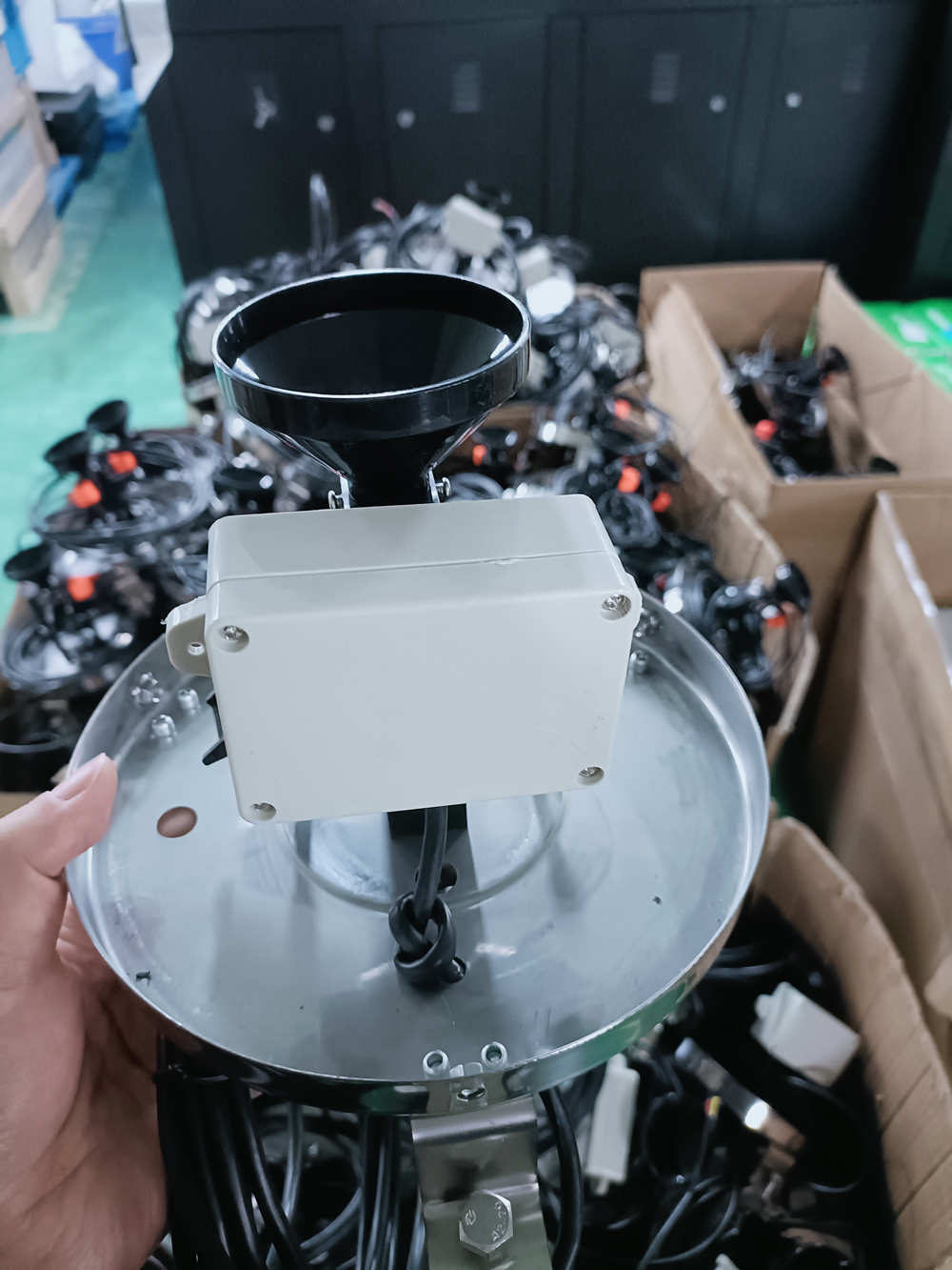
Commission in two stages. First, operate the mechanism using the approved functional method and check that each operation reaches the receiver once. Second, use the specified controlled-water procedure to test the hydraulic collection and metering process. An electrical pulse simulation checks input counting but does not verify the funnel, bucket volume or drain path.
Repeat at suitable controlled rates where the acceptance procedure requires them. Pouring a container of water into the funnel abruptly is not a valid substitute for a defined rate test. Confirm the logger's time base and compare local totals with transmitted records. Then interrupt communications and power separately to see whether the recovered event total remains intelligible.
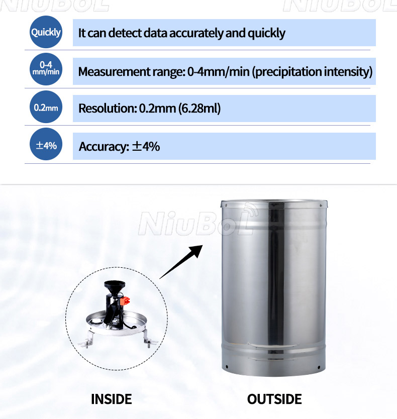
Inspect the funnel, filter, bucket, axle, reed switch, level and mounting after storms and at a frequency suited to leaves, insects and dust at the site. Low readings may result from blockage or under-catch in wind. High or irregular readings may come from vibration, bounce, poor drainage or incorrect logger scaling. In freezing climates, specify a suitable heated instrument or an alternative precipitation method.
For a single collector, the simplest workable arrangement may be a nearby counter and existing RTU. For scattered unmanned locations, local count retention and recoverable communications become more important. Add other weather sensors only when their measurements serve a defined task. Rainfall does not by itself establish river level, reservoir storage or flood arrival time.
A NiuBoL inquiry should identify rainfall resolution, event interval, electrical input, freezing risk, available power and where the data must go. State whether the gauge will join an existing acquisition system or needs a complete station. Separate instrument, installation and reporting costs so quotations can be compared for the same monitoring duty.
No. Rain presence can support an interlock, but it does not supply rainfall depth. Specify accumulated millimeters or intensity explicitly when those values are needed.
Only if the finer increment helps the reporting task and the complete instrument suits the site. Compare intensity response, field exposure, output and maintenance as well as resolution.
No. It is an intensity interval, equivalent to a maximum stated rate of 240 mm/h. Accumulation over time is a separate quantity, with counter capacity and resets handled by the instrument and receiver.
Not as the standard liquid-precipitation arrangement. Select a precipitation method suited to snow and freezing, and account for its energy demand and measurement behavior.
No. A receiving device still has to poll it, interpret values and assign timestamps. Confirm whether the delivered gauge retains data and how the station handles an outage.
A reset or new counter baseline can look like a decrease. Compare the instrument's retained value, receiver restart record and reset settings before diagnosing a hydraulic fault.
Compare the specified gauge, logger or counter, mounting, power, field cable, protection, communications and acceptance work. A collector-only price is not comparable to a complete reporting station price.
A reliable rainfall station is the result of a matched sensor, logger and field method. Resolution, output, siting and maintenance should be agreed before procurement.
Select a rainfall weather station by working from the required record back to the collector and acquisition path. Distinguish rain presence from measured precipitation, resolution from field accuracy, and instrument counts from published event totals. Those choices determine whether the station supplies useful rainfall information after the first storm and the first outage.

Prev:Farmland Weather Station Data Completeness: Check Daily Records
Next:Fertigation Soil EC Monitoring: Interpret Root-Zone Trends
Related recommendations
Sensors & Weather Stations Catalog
Agriculture Sensors and Weather Stations Catalog-NiuBoL.pdf
Weather Stations Catalog-NiuBoL.pdf
Agriculture Sensors Catalog-NiuBoL.pdf
Water Quality Sensor Catalog-NiuBoL.pdf
Related products
 Combined air temperature and relative humidity sensor
 TDR Soil Moisture & Temperature Sensor for irrigation| RS485 |4-20mA| NBL-S-THR
 Soil pH sensor RS485 soil Testing instrument soil ph meter for agriculture |NBL-S-PH
 Wind Speed sensor Output Modbus/RS485/Analog/0-5V/4-20mA
 Tipping bucket rain gauge for weather monitoring auto rainfall sensor RS485/Outdoor/stainless steel
 Pyranometer Solar Radiation Sensor 4-20mA/RS485


Screenshot, WhatsApp to identify the QR code
WhatsApp number:+8615367865107
(Click on WhatsApp to copy and add friends)

