





— Blogs —
—Products—
 Consumer hotline +8618073152920
WhatsApp:+8615367865107
Address:Room 102, District D, Houhu Industrial Park, Yuelu District, Changsha City, Hunan Province, China
Product knowledge
Time:2024-12-03 14:29:50 Popularity:2130
A remote sensor for a weather station is not necessarily a wireless sensor or a direct replacement for an existing transmitter. Before ordering, match the measured quantity, electrical output, supply, wiring, protocol and receiver configuration. A compatible field sensor can report through a logger and remote network; matching the housing, connector or parameter name alone does not establish that compatibility.
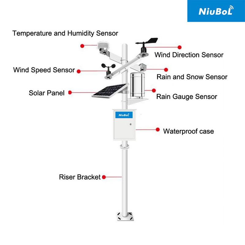
A failed wind channel may originate in the sensor, cable, supply or logger configuration. A complete loss of remote reporting may instead be a network or server problem. Check local acquisition before replacing the field instrument. If all channels disappear together, inspect shared power and communication equipment before assuming several sensors failed simultaneously.
Record the sensor model and output version, receiver model, terminal assignment, supply measured under load, serial settings and recent changes. Keep the existing configuration available. This gives NiuBoL enough information to assess a replacement rather than selecting by a photograph alone.
Wind direction and speed need different instruments. Relative humidity is not soil moisture. Rain presence is not accumulated rainfall. Several channels may be returned by one integrated head, but that does not mean it can replace separate instruments with different exposure or service requirements.
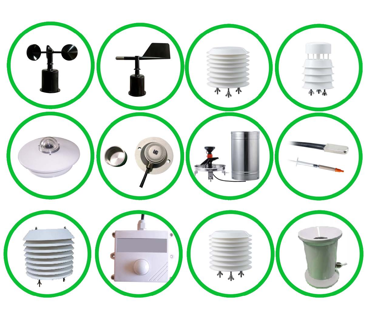
| Example instrument | Quantity and specification | Replacement check |
|---|---|---|
| NBL-W-SS | Wind speed; selected 0-45 or 0-70 m/s; 0.1 m/s resolution | Match range, output, conversion and sampling, not just cup shape. |
| NBL-W-DS | Wind direction; 0-360 degrees; +/-3 degrees | Check north reference, direction convention and output mapping. |
| NBL-W-LBTH | Air temperature, humidity and pressure; selected RS485 or 4-20 mA | Verify all required channels and pressure reference. |
| NBL-W-HPRS | Solar irradiance; 0-2000 W/m2; spectral range 0.3-3 micrometres | Match measurement plane, output and calibration coefficient. |
The NBL-W-HPRS is a thermopile pyranometer with selected analog and optional RS485 outputs. A low-level millivolt version requires appropriate acquisition; it is not equivalent to connecting a powered 0-5 V transmitter. Copying a previous sensor's coefficient can produce a plausible but incorrect irradiance record.
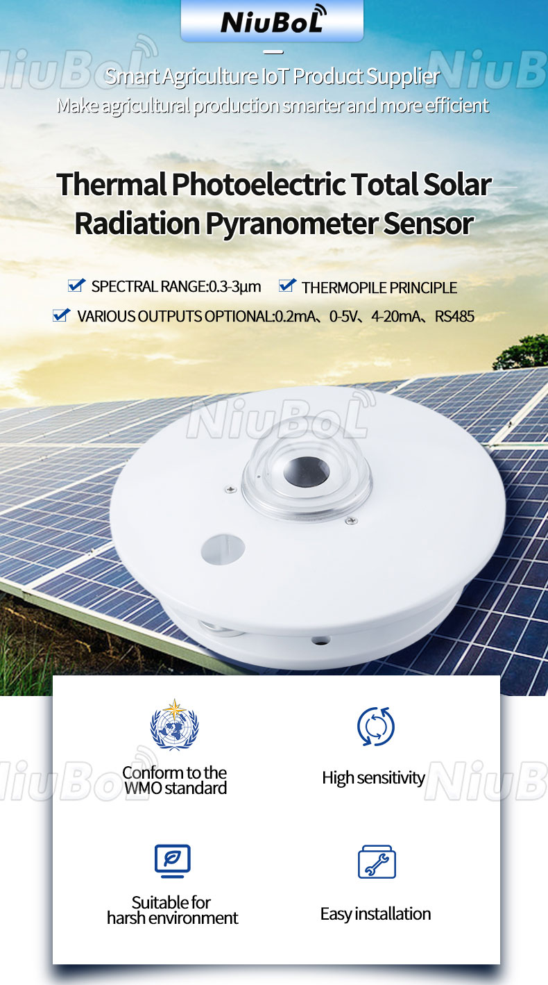
Retain the intended plane and orientation when replacing the instrument. For direct, diffuse or reflected radiation work, identify the actual arrangement and accessories; a general pyranometer does not supply every component simultaneously. Compare reference measurements under the same geometry rather than concluding that different readings always indicate sensor error.
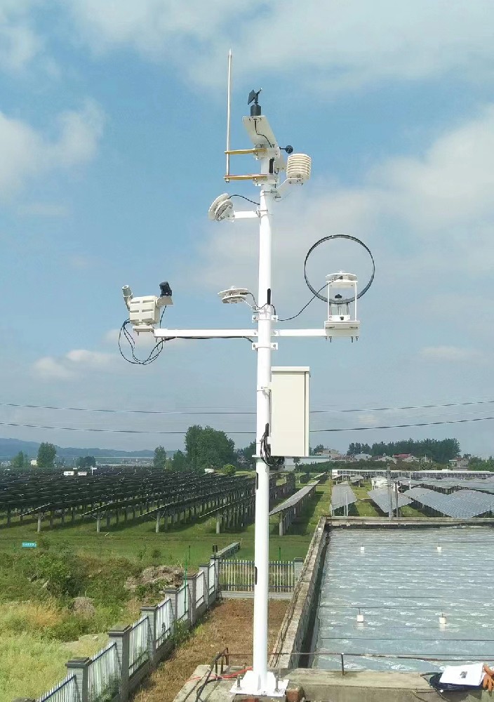
The selected output determines the electrical connection. For example, NBL-W-SS is available with RS485, current, voltage and pulse outputs; supply is DC 5 V or DC 12-24 V according to configuration. NBL-W-DS has selected RS485, 4-20 mA and 0-5 V outputs. Do not apply a supply merely because it powered the removed instrument.
Trace power, signal and reference conductors to their terminals. A connector that fits can still have a different pin assignment. Measure supply at the sensor during operation, check cable condition and follow the applicable isolation and grounding design. Disconnect power before rewiring unless the equipment's service procedure explicitly allows otherwise.
For an RS485 Modbus RTU version, match baud rate, parity, address, supported function, register location, data type, byte order, scaling and unit. Two devices can both use Modbus while returning different register layouts. Replacing a head without updating the logger can turn a valid response into an incorrect displayed value.
On a shared bus, commission the replacement at a unique address. Test it individually before returning it to the full network. Record the old and new mappings, including invalid-value handling. Do not troubleshoot a duplicate address by repeatedly changing unrelated sensor settings.
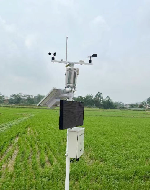
A sensor with an industrial output does not automatically pair with a proprietary weather console. For radio-linked equipment, frequency band alone is insufficient: message format, pairing, network role, firmware support and the receiving device must match. A wireless link at the station also does not eliminate power and local sensor wiring.
If a direct replacement is unavailable, assess whether a new acquisition device can read the selected sensors and export to the existing destination. The TG462 / TG462S family has three RS485 interfaces and two Ethernet ports, with configured analog/digital acquisition and cellular options. Connection to the existing destination requires a supported data format and configuration, rather than universal console emulation.
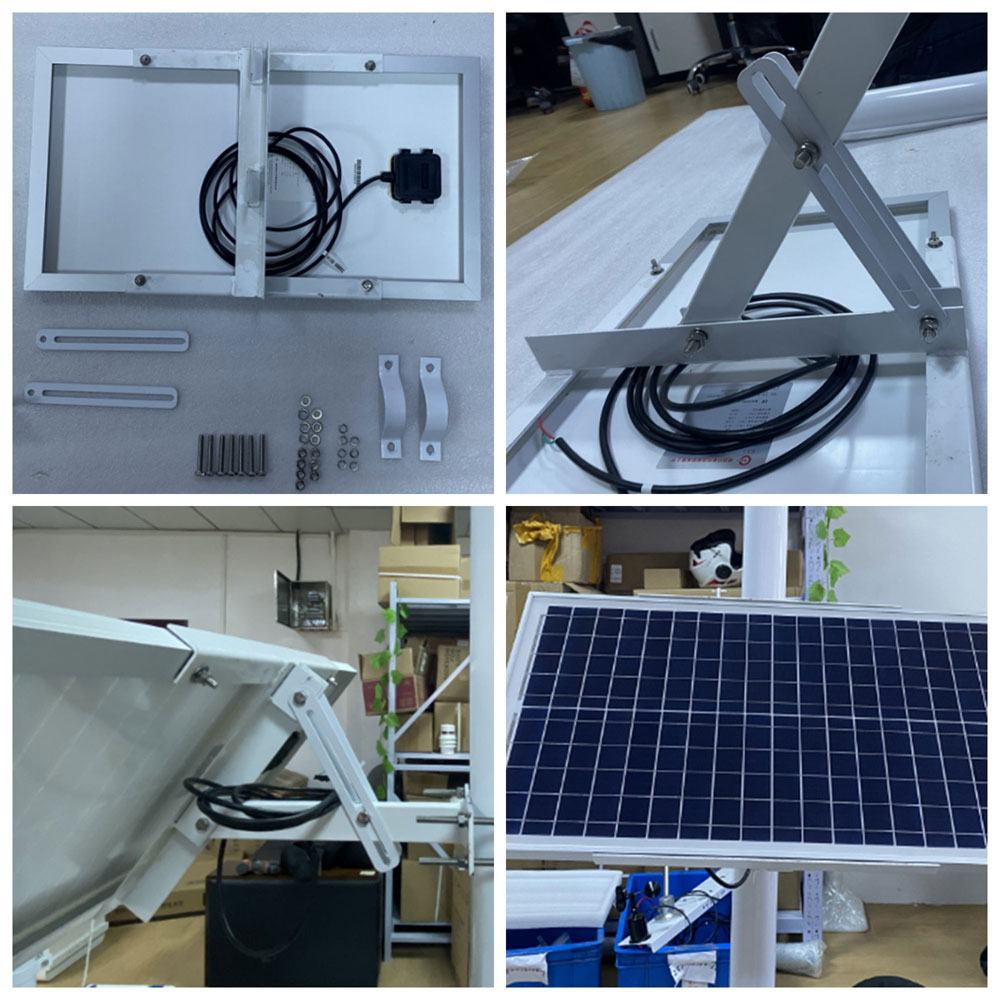
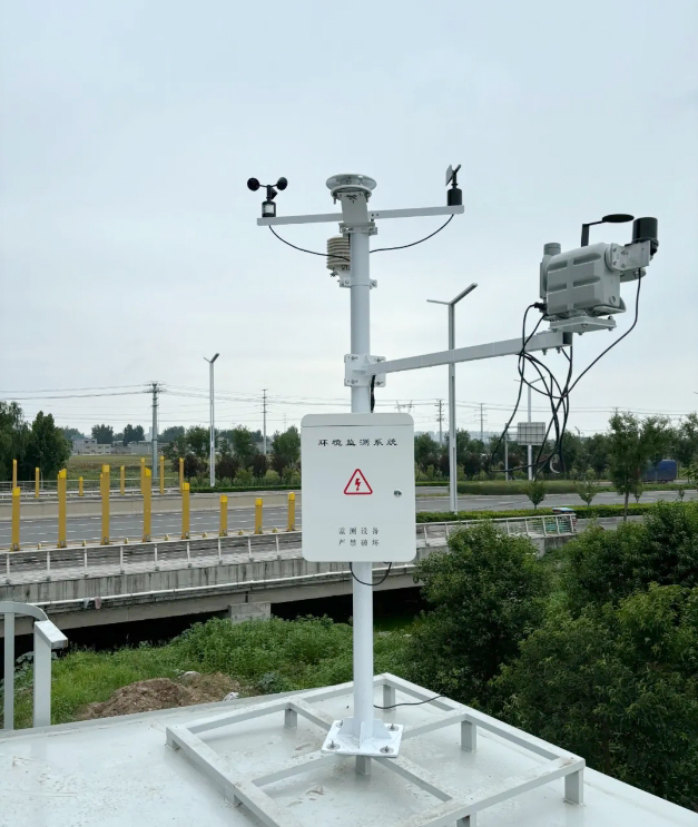
A new bracket must keep the instrument secure without compromising exposure. Retain or deliberately revise wind height, direction reference, radiation plane and rainfall collector level. IP65 is the specified protection requirement for the NBL-W-SS and NBL-W-DS wind sensors; connections and the cabinet still need their own protection.
A change from separate sensors to a combined head can alter measurement positions and maintenance access. If the replacement changes response time or averaging, retain that information with the historical record. The old and new series may differ for a valid measurement reason even when both instruments operate correctly.
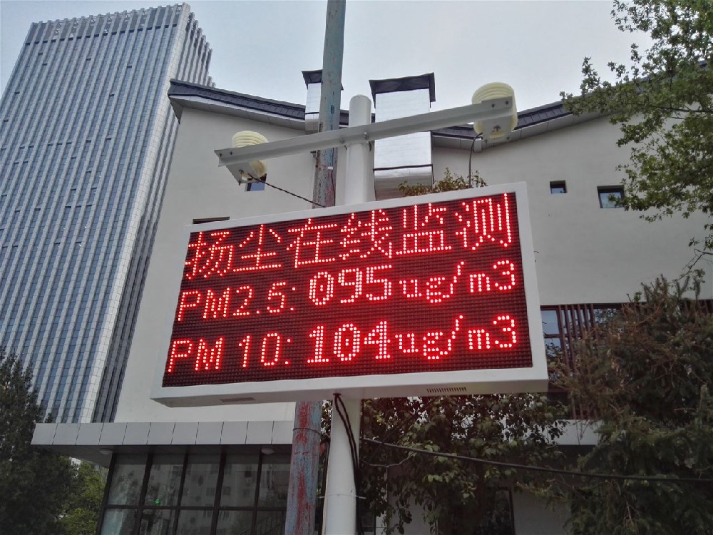
Compare the logger's decoded value with the transmitted record and the final dashboard. Check units, timestamp, station identifier and sensor identity. Introduce a controlled unavailable-channel condition and confirm that the application distinguishes missing data from a valid zero. Restore the instrument and verify recovery.
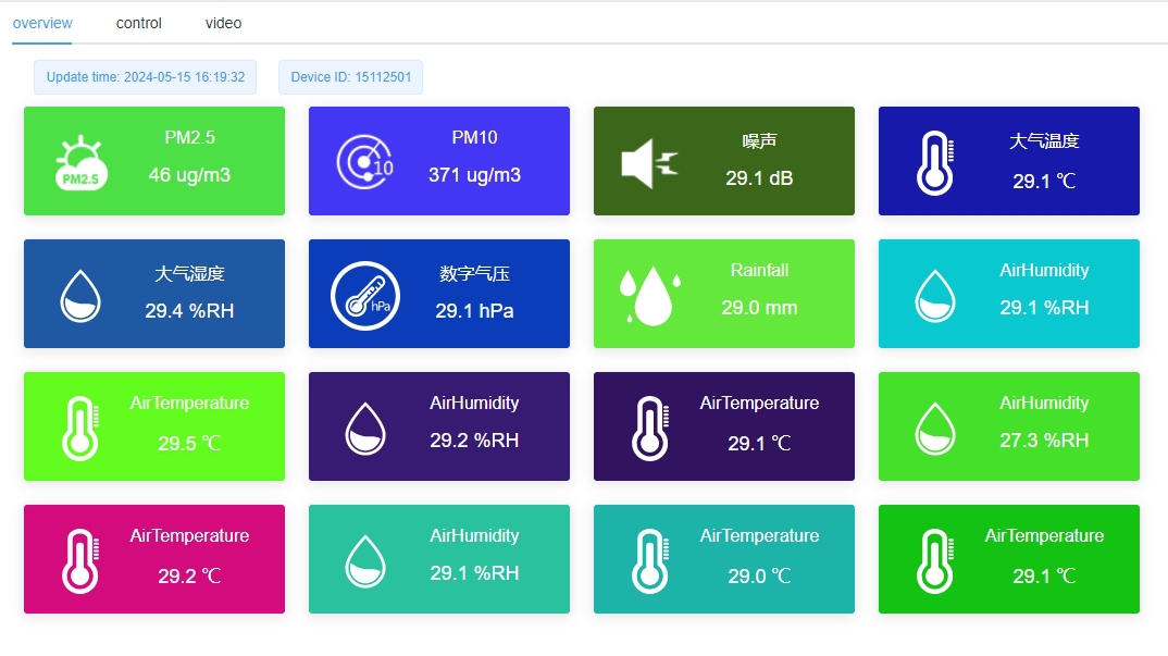
For a remotely connected station, test network loss separately from sensor loss. Buffering, replay and restart retention depend on configured software, not merely on storage hardware. CRC checks on a field message are not encryption. Agree authentication and transport protection for the actual network path, and do not assume every serial or cellular link provides them by default.
Record replacement time, serial or asset identity, configuration revision and any comparison period. Exclude service tests from operational rainfall totals or other accumulations. Do not fill a failed sensor's historical gap with the first healthy reading after replacement.
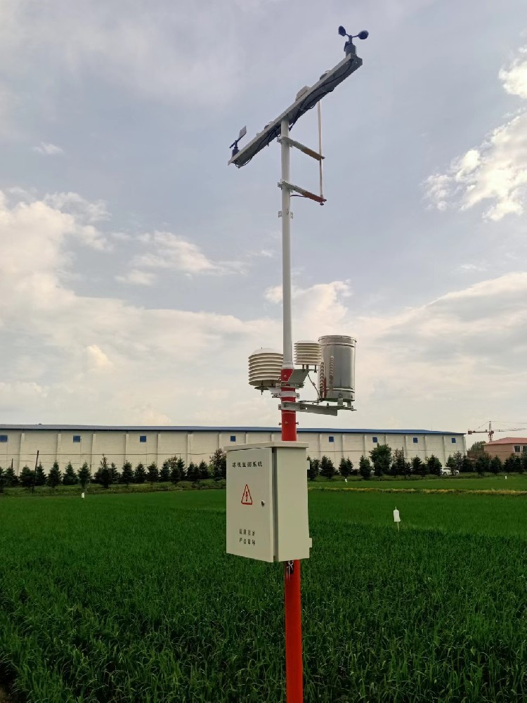
For a quotation, provide the existing output and receiver details, required measurements, site conditions, mounting constraints, available supply and destination system. State whether the request is for one field instrument, a sensor-and-logger retrofit or a complete remote station. This separates a replacement part from an integration project and avoids ordering unused equipment.
Potentially, if the selected version matches the receiver's electrical input and supported interpretation. Provide the receiver model and interface documentation. A shared parameter name or RS485 label is not enough to confirm a direct connection.
No. Wired field sensors can connect to a local logger that reports by Ethernet or a configured wireless network. Identify the sensor-to-logger path separately from the logger-to-server path.
Only if the acquisition system supports the new interface and the required data processing. A pulse counter cannot read Modbus merely by changing the cable. Update the connection, configuration and any accumulation logic deliberately.
Use the coefficient and conversion appropriate to the new instrument and output. Reusing an unrelated coefficient is particularly risky with low-level radiation signals. Verify the decoded unit and range before accepting the dashboard result.
Verify electrical supply, local acquisition, decoded quantities, final records and controlled fault recovery. Check physical alignment and retain changeover records. A visible number on one screen is not enough to accept the full measurement path.
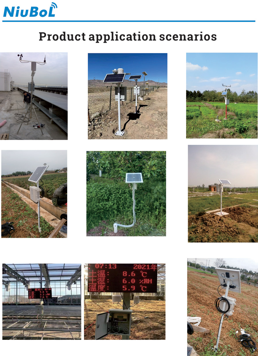
Select a remote sensor for a weather station by compatibility with the actual measurement and receiving system. Identify the failed layer, match the instrument and its output, then verify acquisition and remote records. A documented changeover protects both the new installation and the interpretation of historical data.
Prev:Agriculture Weather Station Price: Budget by Farm Site and Soil Point
Next:Outdoor Weather Station: What the System Measures and What It Does Not
Related recommendations
Sensors & Weather Stations Catalog
 Agriculture Sensors and Weather Stations Catalog-NiuBoL.pdf
Weather Stations Catalog-NiuBoL.pdf
Agriculture Sensors Catalog-NiuBoL.pdf
Water Quality Sensor Catalog-NiuBoL.pdf
Related products
 Combined air temperature and relative humidity sensor
 TDR Soil Moisture & Temperature Sensor for irrigation| RS485 |4-20mA| NBL-S-THR
 Soil pH sensor RS485 soil Testing instrument soil ph meter for agriculture |NBL-S-PH
 Wind Speed sensor Output Modbus/RS485/Analog/0-5V/4-20mA
 Tipping bucket rain gauge for weather monitoring auto rainfall sensor RS485/Outdoor/stainless steel
 Pyranometer Solar Radiation Sensor 4-20mA/RS485


Screenshot, WhatsApp to identify the QR code
WhatsApp number:+8615367865107
(Click on WhatsApp to copy and add friends)

