





— Blogs —
—Products—
 Consumer hotline +8618073152920
WhatsApp:+8615367865107
Address:Room 102, District D, Houhu Industrial Park, Yuelu District, Changsha City, Hunan Province, China
Product knowledge
Time:2025-04-16 20:28:31 Popularity:2513
Tipping bucket rain gauge output selection depends on the receiving equipment and the rainfall record required. A contact or pulse version needs a suitable counter input; a voltage version needs its defined transfer function; an RS485 Modbus RTU version needs correct register interpretation. These are orderable interface configurations, not signals that should be assumed to appear simultaneously on every gauge.
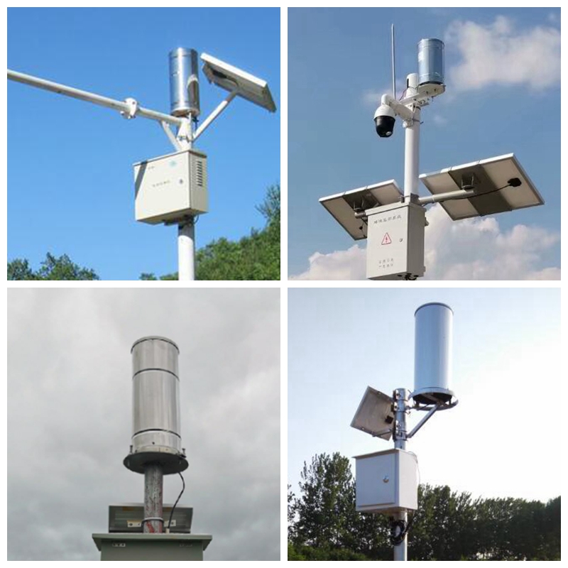
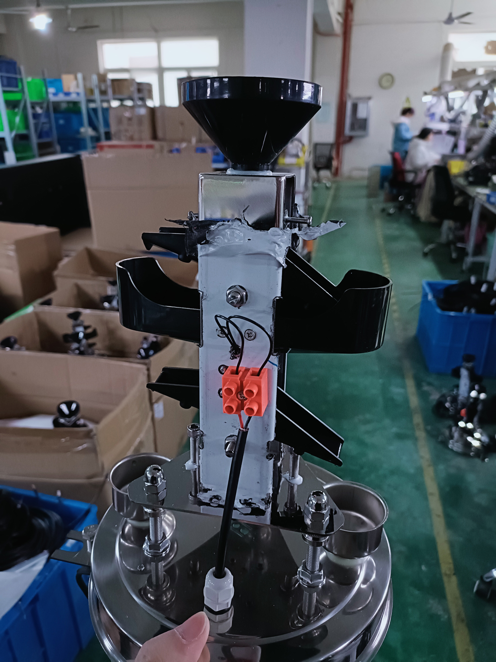
Rain enters the collector and passes to a tipping mechanism. Each counted tip represents a defined rainfall increment for that model. The logger then uses the count and timing to form totals or intensity records. For a raw contact configuration, the bucket itself does not provide a timestamped historical database, mobile connection or a complete flood-warning function.
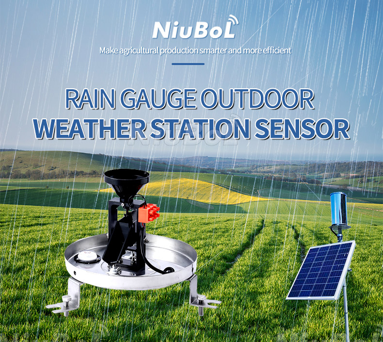
The NiuBoL NBL-W-RS has a 0.2 mm resolution. For its nominal 200 mm inlet diameter, each 0.2 mm increment corresponds to approximately 6.28 ml. The NBL-W-DRS uses a 0.1 mm increment, approximately 3.14 ml with the same nominal inlet diameter. These volumes follow the collector geometry; they are not universal tip volumes for every tipping bucket rain gauge.
Choose the rainfall increment and interface independently. A 0.1 mm mechanism connected to a logger still configured for 0.2 mm per tip can double the reported rainfall. Switching to digital output does not eliminate configuration work: the transmitted value may already be expressed as scaled rainfall rather than a raw tip count.
| Output configuration | Receiving equipment must provide | Main question to resolve |
|---|---|---|
| Reed-switch contact / pulse | Compatible contact-counting input and a defined counting rule | Will it count each physical tip once throughout the required recording period? |
| 0-2.5 V or 0-5 V | Correct analog input range, reference connection and scaling | Which rainfall quantity and full-scale value does the ordered transmitter encode? |
| RS485 Modbus RTU | Compatible serial master, register interpretation and polling schedule | Is the value a count or a scaled rainfall amount, and how does it reset or persist? |
A pulse input is useful when the existing logger already has an appropriate counter and can record events while the main application performs other work. Do not substitute an ordinary slowly scanned digital input without checking its behavior. Confirm whether the supplied contact is passive or uses additional electronics, and use the specified input circuit rather than assuming a universal wiring arrangement.
For voltage output, a measured 1 V is not a rainfall value until the ordered transfer function is known. Establish the meaning of the output, its range and its accumulation or reset behavior. Do not borrow an air-temperature scaling formula or assume that 0-5 V always represents rainfall intensity. The configured transmitter, not the general gauge name, defines that relationship.
RS485 can be convenient for a station that already collects other Modbus instruments. The receiving PLC, RTU or data logger must still understand the data. For the defined rainfall format, an example register value of decimal 26 represents 2.6 mm after division by ten. Multiplying that value again by the bucket increment would apply the conversion twice.
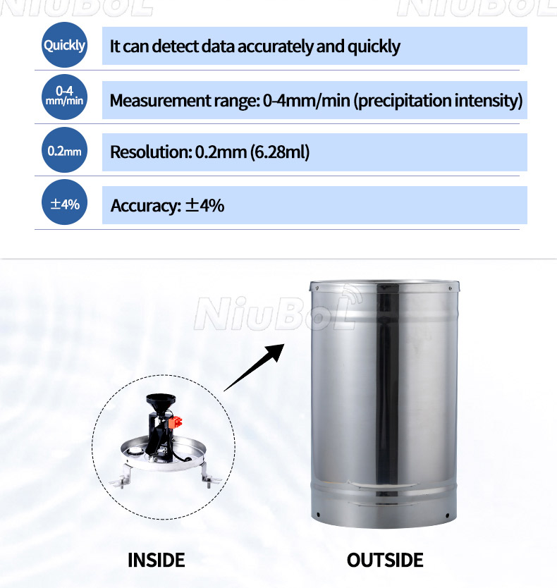
| Parameter | NBL-W-RS | NBL-W-DRS |
|---|---|---|
| Collector inlet | Φ200 ±0.6 mm | Φ200 ±0.6 mm |
| Rainfall-intensity range | 0-4 mm/min | 0-4 mm/min |
| Resolution | 0.2 mm, approximately 6.28 ml | 0.1 mm, approximately 3.14 ml |
| Stated accuracy | ±4% under the stated indoor test at 2 mm/min | ±4% under the stated indoor test at 2 mm/min |
| Supply options | DC 5 V or DC 12-24 V, according to version | DC 5 V or DC 12-24 V, according to version |
| Output options | Reed-switch signal, 0-2.5 V, 0-5 V or RS485 | Reed-switch signal, 0-2.5 V, 0-5 V or RS485 |
| RS485 configuration | Modbus RTU; default 9600 bps; polling at least 1000 ms apart | Modbus RTU; default 9600 bps; polling at least 1000 ms apart |
| Standard cable | 5 m | 5 m |
| Operating temperature | 0°C to 50°C | 0°C to 60°C |
The smaller DRS increment is not a claim of ±0.1 mm accuracy under every field condition. Both listed accuracy statements have specified test conditions. Wind exposure, leveling, contamination and flow through the mechanism can affect a field record. Neither listed unheated operating range establishes measurement of frozen precipitation or operation below freezing.
First verify that a known number of controlled tips appears once each at the receiver. For example, ten valid tips correspond to 2.0 mm for the RS mechanism or 1.0 mm for the DRS mechanism. This is a counting and scale check, not a calibration of how the funnel and bucket respond to natural rainfall.
Next test what happens when the logger restarts or communications stop. A raw contact event cannot be reconstructed later unless some powered part of the installed system counted it. For a digital transmitter, confirm whether the relevant register persists, resets or wraps; do not assume a large cumulative value is a daily total. Record the behavior of the ordered version and implement interval calculations accordingly.
Do not multiply repeated polling results as though each response represented new rain. If a register contains a cumulative amount, successive interval totals require a difference calculation with defined handling of resets and invalid periods. If it contains an interval amount, confirm the interval boundary. Resolve this before combining rainfall with irrigation or drainage records.
Level the gauge using its adjustment points and recheck the bubble after the fixings are tightened. Remove the transport restraint from the tipping assembly before the functional test. A perfectly wired gauge with a restrained bucket can still report no rainfall. Inspect the funnel and outlet for packaging, leaves or insects rather than changing the pulse multiplier to compensate for an obstruction.
Use controlled water delivery for a quantitative test. Define the injected volume, delivery rate, collection area and initial bucket condition. Rapidly emptying a container into the funnel does not establish performance across the gauge's intensity range. Keep manual tipping checks separate from water-delivery tests, because they exercise different parts of the measurement chain.
Install away from roof runoff and splash sources unless those flows, rather than rainfall, are the actual measurement task. A mounting location should allow safe access for clearing the funnel and checking level. The mechanical design does not make the gauge immune to wind or maintenance effects, and a remote connection cannot reveal every blockage without an independent check.
For an irrigation project, a pulse version may be appropriate when a compatible logger already records the count and applies a defined daily boundary. For a distributed environmental station, RS485 may fit the existing instrument bus. An industrial installation limited to analog inputs may prefer a voltage version, but only after the quantity and scale are confirmed.
Keep the rain gauge's role separate from other measurements. It records liquid precipitation, not rainwater chemistry, water level or soil infiltration. Those require additional instruments and methods. Similarly, the rain observation may be one input to a flood-response system, but the gauge alone does not establish an emergency threshold or guarantee a warning.
A useful enquiry identifies the receiving input, required rainfall increment, recording interval, power source, cable route and freezing exposure. Include reset and outage requirements if the project needs continuous event records. These details let NiuBoL specify the appropriate interface without quoting a transmitter that the existing station cannot interpret.
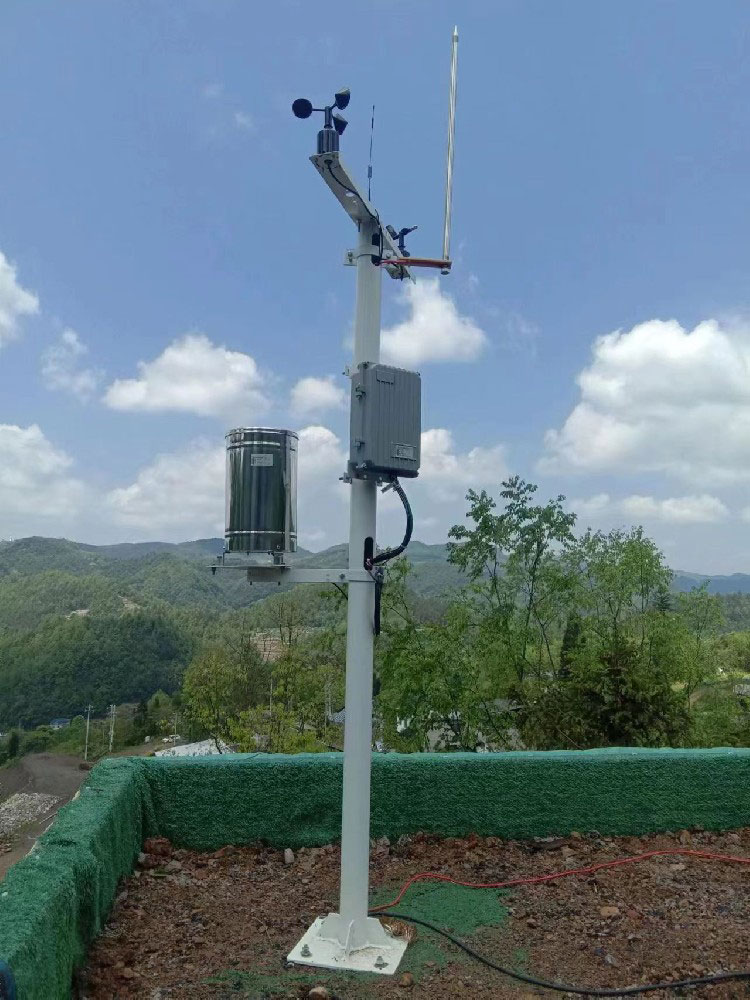
No. A contact version sends switching events for a compatible counter. An RS485 version supplies data through an electronic communication interface. Confirm the ordered output and wiring before connecting either version to an existing logger.
No. It provides a smaller measurement increment than the 0.2 mm RS version. Accuracy remains a separate specification with defined test conditions, and the installation still needs suitable exposure, leveling and water-flow checks.
It does not need a Modbus register map, but it does need the ordered analog transfer function and quantity definition. Confirm input range, full scale and reset behavior; a voltage alone is insufficient to calculate rainfall.
A common configuration error is retaining 0.2 mm per pulse after fitting a 0.1 mm mechanism. Another is converting an already scaled digital rainfall value a second time. Compare the physical increment, transmitted quantity and logger formula separately.
Not automatically. Recovery depends on which parts remained powered, what they counted and whether the relevant value was retained. Verify the actual transmitter and logger behavior. A digital output alone does not establish recovery.
The listed operating ranges begin at 0°C, and freezing can prevent normal liquid flow. A project requiring frozen-precipitation measurement or subzero operation needs a separately specified solution rather than an assumption based on the metal enclosure.
Include rainfall increment, signal version, supply voltage, receiving input, cable and mounting details. For digital output, add register interpretation and required reset or retention behavior. This helps avoid a mechanically compatible replacement that produces an incompatible rainfall record.
Define whether it receives discrete tip events or a cumulative value, and test the restart behavior with a known number of simulated tips. The receiving program must not treat a reset counter as negative rainfall or duplicate the last increment. Record the counter convention in the handover because a replacement logger may interpret the same wire differently.
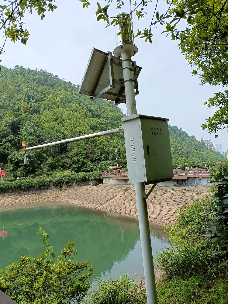
Tipping bucket rain gauge output selection is a measurement-chain decision. Match the RS or DRS increment to the receiving input, verify whether the signal represents tips or rainfall, and test counting separately from water collection. The resulting record is useful only when its timing, scaling and outage behavior are understood.
 NBL-W-ARS-Tipping-bucket-rain-gauge-instruction-manual.pdf
NBL-W-RS-Rain-sensors-instruction-manual-V4.0.pdf
NBL-W-DRS-Double-Tipping-Bucket-Rain-Sensor-Instruction-Manual.pdf
Related recommendations
Sensors & Weather Stations Catalog
Agriculture Sensors and Weather Stations Catalog-NiuBoL.pdf
Weather Stations Catalog-NiuBoL.pdf
Agriculture Sensors Catalog-NiuBoL.pdf
Water Quality Sensor Catalog-NiuBoL.pdf
Related products
 Combined air temperature and relative humidity sensor
 TDR Soil Moisture & Temperature Sensor for irrigation| RS485 |4-20mA| NBL-S-THR
 Soil pH sensor RS485 soil Testing instrument soil ph meter for agriculture |NBL-S-PH
 Wind Speed sensor Output Modbus/RS485/Analog/0-5V/4-20mA
 Tipping bucket rain gauge for weather monitoring auto rainfall sensor RS485/Outdoor/stainless steel
 Pyranometer Solar Radiation Sensor 4-20mA/RS485


Screenshot, WhatsApp to identify the QR code
WhatsApp number:+8615367865107
(Click on WhatsApp to copy and add friends)

