





— Blogs —
—Products—
 Consumer hotline +8618073152920
WhatsApp:+8615367865107
Address:Room 102, District D, Houhu Industrial Park, Yuelu District, Changsha City, Hunan Province, China
Product knowledge
Time:2026-09-09 15:00:00 Popularity:216
Quick Answer: An automatic soil moisture data station combines permanently installed probes, a logger, power and a data connection. Specify it by irrigation zone and measurement depth, not by the number of sensors advertised. The station should preserve each probe's location and depth through to the dashboard. Automatic recording does not, by itself, include automatic valve control.
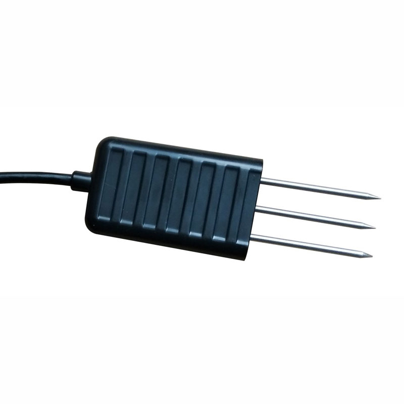
A single probe measures the soil close to its electrodes. It cannot represent every bed, slope or irrigation circuit simply because its value is uploaded to a platform. Separate monitoring points by soil type, irrigation zone, terrain and crop management. One convenient point should not be assumed to represent a large or variable field.
For an illustrative orchard layout with three independently irrigated blocks, two depths in each block would require six soil probes. If each probe measures moisture and temperature, the database needs twelve measurement channels, even though there are only six physical devices. This distinction affects logger configuration, dashboard labels and the quotation. More depths do not compensate for putting every probe in an unrepresentative corner.
Choose the upper depth to follow the active root zone and a deeper position to investigate wetting below it. Exact depths depend on rooting, soil horizons and irrigation method; a standard pair of depths is not suitable for every crop. Under drip irrigation, record the horizontal distance from the emitter as well. Moving a probe across the wetting pattern can change its response without any change in sensor performance.
| Part of the station | What it does | What must be included separately |
|---|---|---|
| Buried moisture and temperature probes | Measure conditions at defined points and depths | Mounting work, cable protection and a location plan |
| Data logger or RTU | Poll sensors and associate readings with time and channel identity | Required storage, clock settings and compatible sensor drivers |
| Gateway or integrated modem | Transfer records to the chosen destination | Network service, platform connection and outage recovery configuration |
| Power system and enclosure | Keep field electronics operating outdoors | Battery autonomy, charging equipment, cable glands and protective devices |
| Irrigation controller, when required | Apply approved rules to valves or pumps | Actuator interfaces, independent safeguards and manual override |
A sensor-only order is appropriate when an existing controller already provides these functions. For a new remote site, omitting the logger, power system or data connection leaves an incomplete station. Conversely, buying a second cloud gateway is unnecessary when the farm already has a compatible local network and wants to retain its existing software.
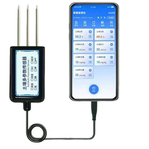
A handheld or phone-connected soil tester has a different role: surveys, spot measurements and investigation around a fixed station. It should not be specified as an unattended station unless the complete device arrangement is designed for that duty. The Android-connected soil instrument below is a portable option, not the fixed station's logger.
The NiuBoL NBL-S-TM soil temperature and moisture sensor uses a dielectric FDR measurement for soil water content and provides a separate temperature reading. Its RS485 interface suits a wired station with several probes. This is a point sensor: a multi-depth installation requires several suitably positioned probes or a dedicated profile sensor.
| NBL-S-TM parameter | Specification | Design consequence |
|---|---|---|
| Moisture range and resolution | 0-100% volumetric water content; 0.1% resolution | Keep VWC units; this is not air relative humidity |
| Moisture accuracy | Nominal 5%; agree the percentage basis and test conditions for acceptance | Resolution is not an assurance of field accuracy in every soil |
| Temperature | -40 to 80 deg C; 0.1 deg C resolution; +/-0.5 deg C accuracy | Keep the temperature channel associated with its measurement depth |
| Power input | 5-24 V DC or 12-24 V DC, depending on version | Identify the supplied version before designing a low-voltage supply |
| Signal | RS485, Modbus communication; default 9600 bps | Use the exact register definition and serial settings |
| Probe body protection | IP68; epoxy-sealed construction | External joints and logger protection remain separate requirements |
| Operating environment | -40 to 85 deg C | The operating limit does not extend the temperature measurement range |
| Cable and electrodes | 5 m standard cable; corrosion-resistant electrodes | Specify extension length and cable-jacket suitability for the installation |
Do not transfer these values to another soil model. In particular, a 4-20 mA controller needs an explicitly selected analog-output instrument; it cannot read this RS485 version through an analog input. Sensor power consumption also needs to be included in the station load calculation. A voltage rating alone does not establish battery life.
In the system, each probe sends data to a field logger, irrigation controller or RTU. On the wired side, allocate distinct device addresses and use a planned RS485 trunk with termination appropriate to the actual bus. On the software side, use persistent labels such as block, location and depth. A replacement probe may receive a new serial number without changing the historical identity of the measurement point.
For the NBL-S-TM, allow at least 1000 ms between communications as required by its interface timing. Its example data uses tenths: a moisture value of 176 represents 17.6% VWC. Temperature requires signed decoding when negative. A reserved invalid value such as 0x7FFF must become a missing or faulted reading, not an implausibly high moisture value. Check these cases before using the data in irrigation rules.
Logging and uploading can use different intervals. A logger might collect a five-minute record and upload a group every thirty minutes, but the platform must retain the original measurement times. Labelling all six records with the upload time would hide the wetting sequence. During a network interruption, local storage and later forwarding are useful only if the selected logger actually supports them and recovery is tested.
For buried probes, expose a soil face at the intended depth and insert the electrodes into the undisturbed wall with close contact along their length. Avoid stones, large voids and rocking the probe to enlarge its hole. Replace excavated material without creating a loose vertical path that channels water straight to the sensor. Route and mark cables away from cultivation tools and maintain a retrievable station plan.
Do not water the measurement point solely to obtain a more reassuring commissioning value. That would change the condition the station is supposed to observe. Instead, document the initial condition, allow disturbance to settle and observe the response during a normal irrigation or rainfall event. A nearby comparison sample should represent the same depth and soil, without disturbing the probe's immediate measurement volume.
Interpret the upper and lower traces together. A rapid rise at the upper depth followed later by a deeper response is consistent with downward wetting, but it does not establish an exact drainage volume. A sudden isolated jump after cultivation may indicate displacement or a new air gap. Soil texture, bulk density, salinity and installation quality can all affect interpretation; a factory calibration does not eliminate these site effects.
Adding rainfall helps distinguish irrigation from natural wetting. Air temperature and relative humidity describe the above-ground environment, while a suitable radiation and wind package may support a separately defined evapotranspiration calculation. None of these sensors measures root-zone water content. Select the additional channels only when the operating team will use them.
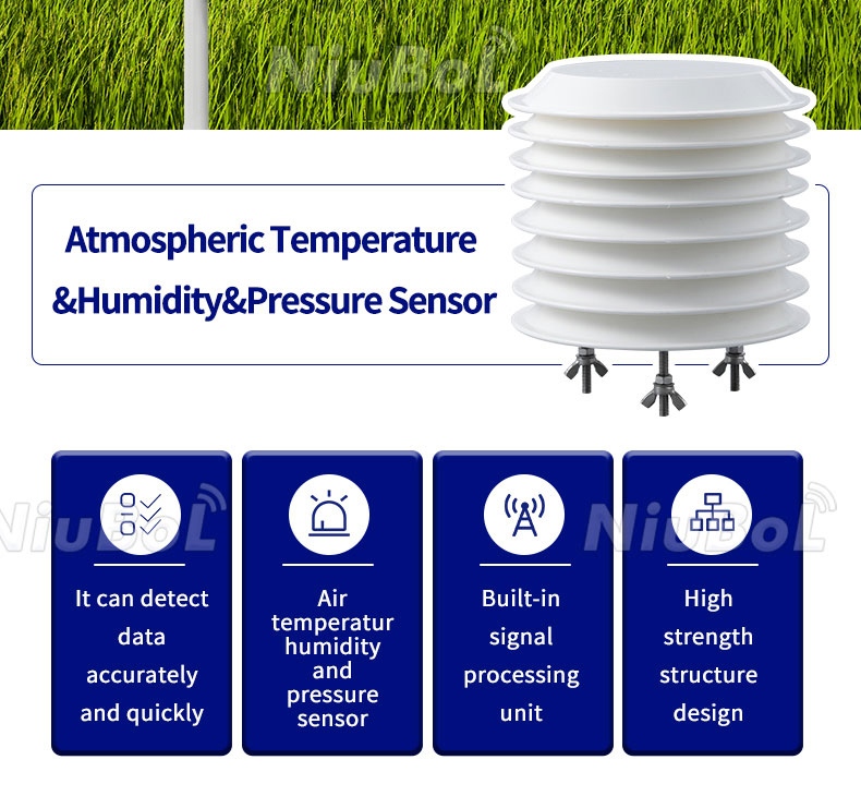
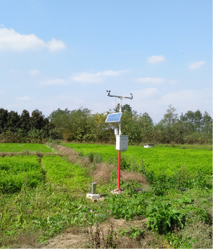
The louvered sensor below is an atmospheric instrument. It belongs above ground with suitable exposure, not in the soil profile. Likewise, a farmland weather station can share a logger with soil probes, but its weather sensor placement should not be chosen merely to shorten the soil cable. A combined installation may need separate mounting positions within one monitoring site.
For a worked example, assume a complete station averages 2 W, including its logger and communications. Its daily demand is 48 Wh. Three days without useful charging require 144 Wh delivered to the load. At an illustrative 80% usable battery fraction and 90% conversion efficiency, nominal battery energy would be at least 144 / (0.8 x 0.9) = 200 Wh before allowances for temperature, ageing and recovery charging. These are design assumptions, not NiuBoL station ratings.
Storage needs a similarly explicit calculation. Twelve channels recorded every five minutes produce 288 time steps per day and 3,456 individual channel values. A device may count one timestamped group as one record, or count every channel separately. Ask which definition applies before translating a storage-capacity claim into days of autonomy. Check what happens when capacity is reached and whether backfilled records create duplicates.
First verify channel identity at the bench: each connected probe must appear under its assigned location and depth. Next install the probes and review a normal irrigation cycle. Then interrupt the network without interrupting measurement, restore it and inspect the recovered timestamps. Finally, simulate a disconnected probe and confirm that the platform marks stale data rather than displaying the last value indefinitely as current.
If automatic watering is included, treat it as a separate commissioning stage. Sensor faults, low battery and lost communications need defined controller responses. A valve should not remain open merely because a dry reading stopped updating. Maximum run time, manual override and flow or pressure checks should be selected with the irrigation designer. Moisture monitoring alone does not verify that a valve opened or water reached the correct circuit.
The number depends on crop rooting depth, soil profile and irrigation method. Two or more depths often show whether water reaches the active root zone or moves below it. However, additional depths at one location do not replace separate monitoring points for different soil types or independently irrigated blocks.
Yes, if the logger has sufficient device and channel capacity and the cable or wireless arrangement suits the distances. Keep each zone separate in the database and irrigation logic. Averaging a dry block with a wet block can hide both conditions and produce an inappropriate watering decision.
No. RS485 describes the electrical interface. Successful integration also requires compatible Modbus RTU reads, serial settings, addressing, scaling and invalid-data handling. Test the actual probe with the selected logger before ordering a large network, especially when combining several sensor families.
Not where a suitable protected supply is available. Solar power is useful for remote sites, but the panel and battery must cover the measured load, seasonal sunlight and the required autonomy. A large panel does not compensate for an undersized battery during a multi-day charging interruption.
Send a zone sketch, proposed depths, probe count, cable distances, power availability and the intended data destination. State whether the order is for sensors, a recording station or an irrigation-control package. NiuBoL can then separate the probes, logger, communications, power and installation accessories without pricing functions already available at the site.
Check whether the change coincides with rain, irrigation, cultivation, cable work or a configuration update. Compare adjacent depths and inspect data freshness before recalibrating. If a soil comparison is needed, use the same moisture basis; gravimetric water content cannot be compared directly with volumetric output without accounting for bulk density.
An automatic soil moisture data station is useful when every record remains tied to a representative location and depth. Begin with the field layout, select compatible probes and verify the complete recording path. Add weather channels or valve control only where they answer a defined operating need. For configuration review, send NiuBoL the zone layout and required measurement depths alongside the logger or platform already in use.
Prev:Forest Fire Weather Station: Parameters, Installation and Alarm Design
Next:What Is a Soil Water Potential Sensor and When Should Projects Use One?
Related recommendations
Sensors & Weather Stations Catalog
 Agriculture Sensors and Weather Stations Catalog-NiuBoL.pdf
Weather Stations Catalog-NiuBoL.pdf
Agriculture Sensors Catalog-NiuBoL.pdf
Water Quality Sensor Catalog-NiuBoL.pdf
Related products
 Combined air temperature and relative humidity sensor
 TDR Soil Moisture & Temperature Sensor for irrigation| RS485 |4-20mA| NBL-S-THR
 Soil pH sensor RS485 soil Testing instrument soil ph meter for agriculture |NBL-S-PH
 Wind Speed sensor Output Modbus/RS485/Analog/0-5V/4-20mA
 Tipping bucket rain gauge for weather monitoring auto rainfall sensor RS485/Outdoor/stainless steel
 Pyranometer Solar Radiation Sensor 4-20mA/RS485


Screenshot, WhatsApp to identify the QR code
WhatsApp number:+8615367865107
(Click on WhatsApp to copy and add friends)

