





— Blogs —
—Products—
 Consumer hotline +8618073152920
WhatsApp:+8615367865107
Address:Room 102, District D, Houhu Industrial Park, Yuelu District, Changsha City, Hunan Province, China
Product knowledge
Time:2026-08-15 09:04:00 Popularity:280
Quick answer: A dissolved oxygen meter for wastewater measures the water at its sensing cap. In a bypass, that water may no longer have the same oxygen concentration as the tank: transfer time, air entry, deposits and changing temperature can affect it. Use a bypass only after demonstrating that its result represents the process point closely enough for the intended decision. The NiuBoL optical probes discussed here are immersion instruments; a compatible pressure-rated holder and sample circuit require separate review.
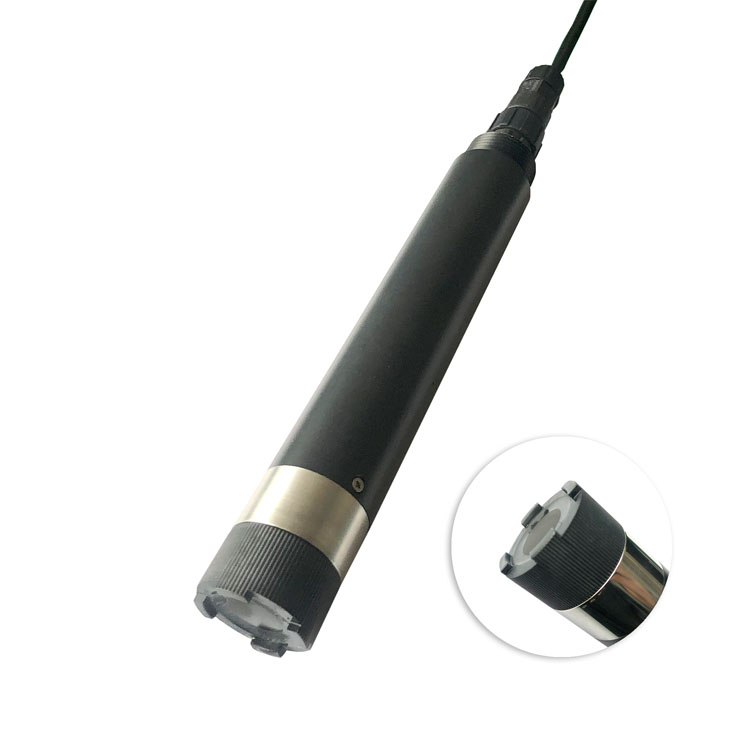
A cabinet-mounted sample panel can make a difficult tank easier to service. It also introduces tubing, valves and a flow chamber between the process and the probe. A clear digital reading at the panel does not establish that this path preserves the original dissolved oxygen.
First identify the decision. If the value will adjust aeration in a particular basin, compare the bypass with that basin at a representative depth and location. A sample taken downstream, after a drop or from a return line may answer a different question. For monitoring final effluent, the relevant comparison is the effluent point, not an aeration-basin reading.
The optical method does not consume oxygen, so these probes do not need flow to replace oxygen consumed at the sensing surface. That does not make stagnant sample tubing acceptable. A bypass still needs representative sample renewal, and solids must not accumulate around the cap. Avoid borrowing the minimum-flow requirement of an electrochemical electrode for an optical model.
| Sample-path condition | What to examine | Decision before installation |
|---|---|---|
| Suction-side air entry | Loose joints, pump suction and visible bubbles | Correct the source of air; do not calibrate around an aerated sample |
| Long tubing or low turnover | Internal liquid volume and measured delivered flow | Estimate transport delay, then confirm actual recovery after a change |
| Pressure change | Normal operation, isolation and pump transients | Keep probe, holder, seals and tubing within their individual limits |
| Settling or deposits | Low points, dead legs and access for flushing | Provide a serviceable route without filtering away the process condition being studied |
| Discharge arrangement | Backpressure, air exposure and approved disposal route | Assess the complete circuit, not just the sensor chamber |
For an initial delay estimate, divide the liquid volume upstream of the sensing point by the measured sample flow. An illustrative 1 L path at 0.5 L/min has a nominal 2-minute transport time. This calculation is not a guaranteed response time: mixing, dead volume and oxygen changes in the line remain to be tested. Neither volume nor flow in this example is a product specification.
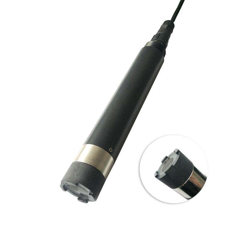
The base NBL-WQ-DO and DO-4A are different versions. Their accuracy statements and operating temperatures should not be interchanged. In particular, resolution is not accuracy, and a full-scale specification must not be rewritten as a percentage of the current reading.
| Item | NBL-WQ-DO | NBL-WQ-DO-4A |
|---|---|---|
| Principle / range | Fluorescence quenching; 0-20.00 mg/L | Fluorescence quenching; 0-20.00 mg/L |
| DO accuracy | +/-2% F.S.; equivalent to +/-0.4 mg/L over this span | +/-2% of reading |
| Resolution / temperature accuracy | 0.01 mg/L; +/-0.3 C | 0.01 mg/L; +/-0.3 C |
| Working conditions | 0-45 C; pressure below 0.2 MPa | 0-50 C; pressure at or below 0.2 MPa |
| Supply / consumption | 12-24 VDC; below 0.3 W at 12 V | 12-24 VDC; 0.2 W at 12 V |
| Output | RS485 Modbus RTU | RS485 Modbus RTU; optional 4-20 mA |
| Compensation | Pt1000 temperature; configured salinity correction | Pt1000 temperature; configurable salinity compensation |
| Protection / installation | IP68; immersion, 3/4-inch NPT | IP68; submerged installation |
The base model has a standard 5 m cable. Confirm the ordered DO-4A cable length, jacket material and holder dimensions rather than transferring them from another version. IP68 does not approve an arbitrary pressurized flow cell. The cap must remain submerged, unobstructed and protected from mechanical damage.
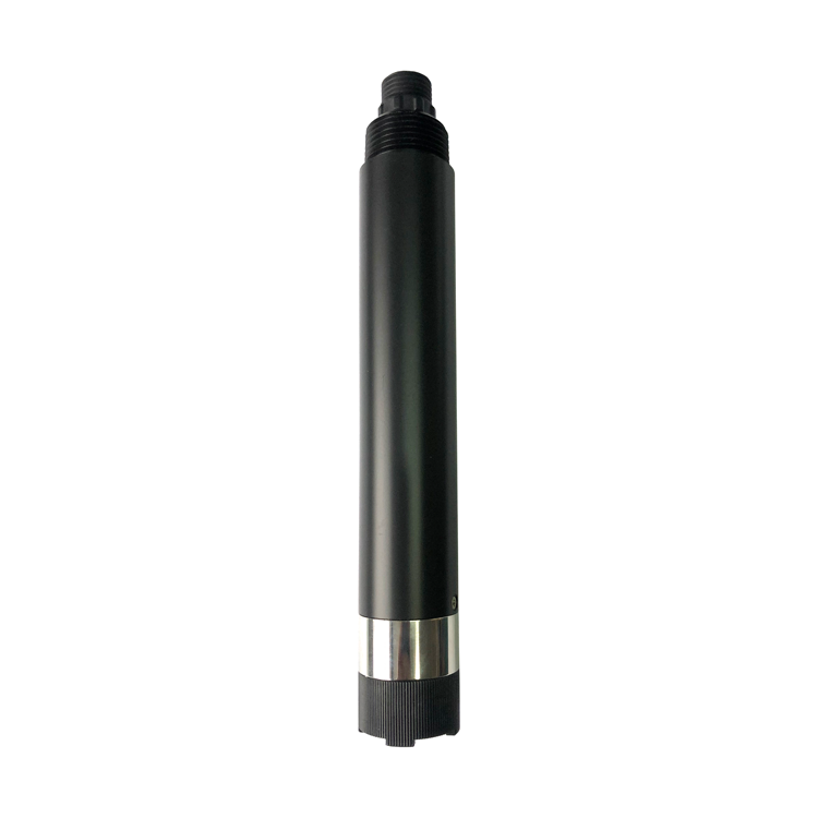
RS485 Modbus RTU provides the data link, not proof of sample validity. In the PLC or data logger, keep the DO value, temperature, acquisition time and communication state distinguishable. If sample flow is critical, provide an independently verified way to detect its loss; do not assume that a plausible DO value proves circulation.
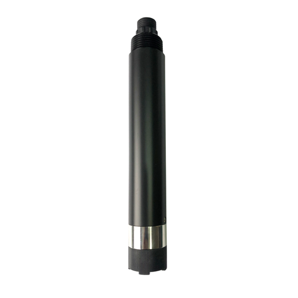
The DO-4A shown below is an alternative probe, not a complete bypass assembly. Its optional current output also needs the ordered range and receiver scaling confirmed.
Only when the bypass preserves the required measurement and offers useful service access. Direct immersion avoids sample-transfer changes but needs safe retrieval and a representative position. Compare both arrangements against the actual operating decision.
Air entry or other changes along the sample route can alter the water reaching the cap. Inspect the circuit and compare at the takeoff before treating a difference as sensor calibration error.
No. It removes the need to replenish oxygen consumed by the measurement, but the sample must still represent the process. Check renewal, deposits, bubbles and delay.
No. Review the probe, holder, tubing, seals and valves separately, including transient conditions. A threaded connection or IP68 label is not a panel pressure approval.
Send the takeoff and discharge drawing, wastewater characteristics, temperature, operating and transient pressures, expected sample flow, access restrictions and controller interface. Ask NiuBoL to distinguish the probe from separately reviewed mounting and sampling components.
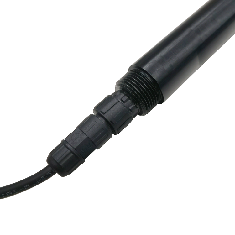
Selecting the probe is only part of a wastewater DO bypass design. The decisive test is whether the sample circuit preserves the process information within the required timing and uncertainty. Where that cannot be demonstrated, improve the sampling arrangement or use representative direct immersion before relying on the result.
Prev:TDS pH Temperature Meter: Investigate Different Probe Temperatures
Next:Insect Monitoring System: Which Species Can a Trap Identify?
Related recommendations
Sensors & Weather Stations Catalog
 Agriculture Sensors and Weather Stations Catalog-NiuBoL.pdf
Weather Stations Catalog-NiuBoL.pdf
Agriculture Sensors Catalog-NiuBoL.pdf
Water Quality Sensor Catalog-NiuBoL.pdf
Related products
 Combined air temperature and relative humidity sensor
 TDR Soil Moisture & Temperature Sensor for irrigation| RS485 |4-20mA| NBL-S-THR
 Soil pH sensor RS485 soil Testing instrument soil ph meter for agriculture |NBL-S-PH
 Wind Speed sensor Output Modbus/RS485/Analog/0-5V/4-20mA
 Tipping bucket rain gauge for weather monitoring auto rainfall sensor RS485/Outdoor/stainless steel
 Pyranometer Solar Radiation Sensor 4-20mA/RS485


Screenshot, WhatsApp to identify the QR code
WhatsApp number:+8615367865107
(Click on WhatsApp to copy and add friends)

