





— Blogs —
—Products—
 Consumer hotline +8618073152920
WhatsApp:+8615367865107
Address:Room 102, District D, Houhu Industrial Park, Yuelu District, Changsha City, Hunan Province, China
Product knowledge
Time:2026-08-24 09:08:00 Popularity:352
Quick Answer: Choose an inline dissolved oxygen sensor by both measurement method and installation assembly. Optical sensing avoids electrolyte and oxygen consumption, but it does not remove bubbles, sample changes or pressure limits. A threaded immersion probe needs a suitable engineered holder or flow-through arrangement before it becomes a dependable pipe measurement point.
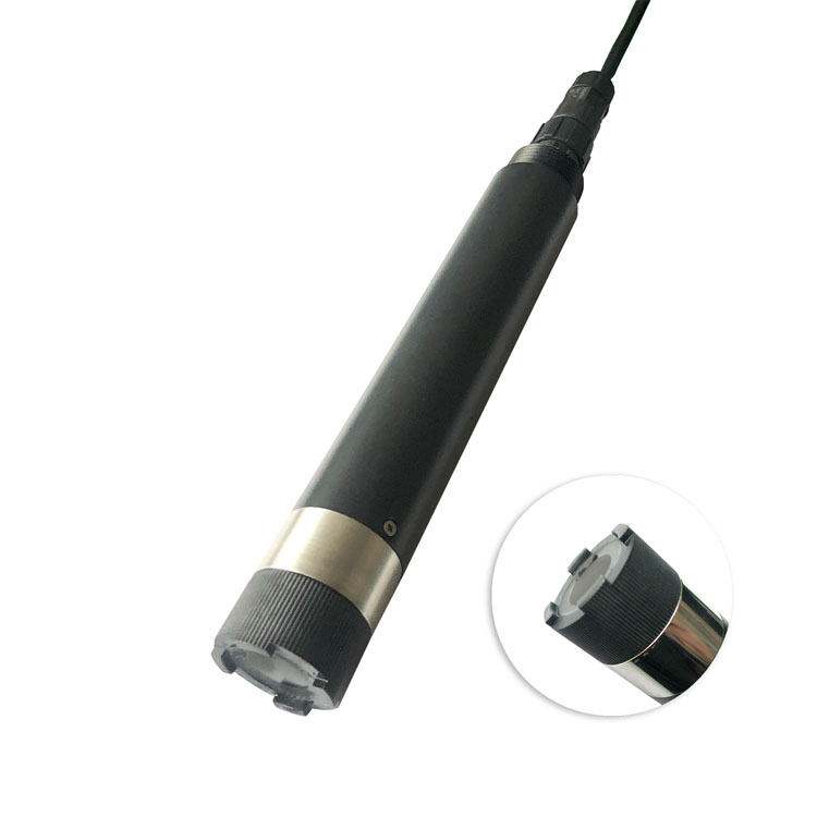
An optical sensor measures the oxygen-dependent response of a luminescent material. An amperometric membrane-covered sensor measures an electrochemical response as oxygen passes through a membrane. The methods differ in oxygen consumption and service requirements, but neither method alone defines the allowable pipe pressure or how the assembly can be removed.
| Question | Optical method | Amperometric membrane method |
|---|---|---|
| Does sensing consume oxygen? | No oxygen consumption by the measurement | The electrochemical measurement consumes oxygen |
| How does flow matter? | No oxygen-consuming boundary-layer demand; representative sample delivery still matters | Follow the instrument's flow requirement to avoid depletion at the membrane |
| What service parts need review? | Optical cap, seals and the specified replacement check | Membrane, electrolyte and other model-specific service parts |
| Is it ready immediately after any service? | Follow the cap and calibration procedure | Follow the model's preparation and any polarisation procedure |
| Does it approve the pipe fitting? | No; review the complete mechanical assembly | No; review the complete mechanical assembly |
Optical sensing can suit a continuous point where reducing electrolyte and membrane work matters. A maintained electrochemical installation can remain suitable where its performance and service arrangements meet the process. Do not replace a functioning method solely on a general claim that one technology always produces better plant results.
The USGS dissolved oxygen field manual distinguishes optical and amperometric methods and explains the influence of sampling conditions. Its environmental field procedures do not certify a particular industrial probe or pressure fitting. Apply the selected instrument's limits and the site's engineering requirements to the actual pipe point.
Direct insertion can avoid a long external sample route, but it places the probe and holder at the process pressure and temperature. Confirm the wetted materials, sealing arrangement, mechanical retention and safe service method. An ordinary threaded opening is not automatically a retractable assembly.
A bypass can make service more accessible, but water transport can alter the observation. Oxygen can change through gas exchange, leakage, biological activity or temperature change along the path. A chamber showing a stable value may be measuring stagnant or altered water rather than the current process.
Decide where the pressure is controlled and measured in a bypass. A pressure reduction upstream can allow dissolved gas to form bubbles, while an open outlet can expose the sample to air. Assess those effects before assuming a lower-pressure chamber gives an equivalent DO value. Do not add an open degassing step without considering that it can change the oxygen condition being measured.
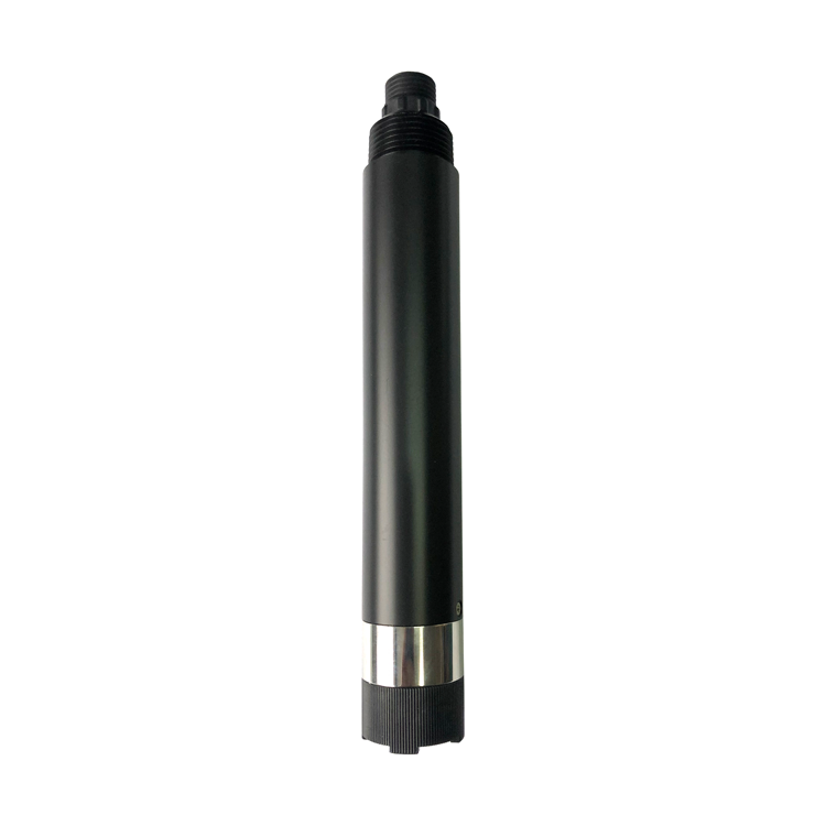
The NBL-WQ-DO fluorescence probe is an immersion instrument with the following limits. They are not a specification for an entire pipe spool, isolation valve or retractable holder. Any proposed inline use needs the complete assembly checked before ordering.
| Item | NBL-WQ-DO configuration | Pipe-point consequence |
|---|---|---|
| Measurement and range | Fluorescence; 0-20 mg/L | Confirm the operating band and required accuracy |
| Resolution and accuracy | 0.01 mg/L; +/-2% full scale | Display increments do not define low-level measurement uncertainty |
| Temperature | 0-45 degrees C operating range; Pt1000 compensation | Do not assume compatibility with a hot cleaning cycle |
| Operating pressure | Below 0.2 MPa | Review actual pressure, transients and every wetted fitting |
| Supply and consumption | 12-24 V DC; less than 0.3 W at 12 V | Provide an appropriate supply outside the wet process connection |
| Output | RS485 Modbus RTU | Use a compatible receiving interface and model-specific data definition |
| Body and protection | POM and 316L stainless steel; IP68 | Check chemical compatibility; IP68 is not a pipe-assembly pressure rating |
| Cable | Standard 5 m; other lengths by agreement | Keep external joints protected and allow safe removal |
For context, 0.2 MPa equals 2 bar. The operating condition is below that limit; it is not permission to run at 2 bar continuously. Do not interpret the immersion rating as proof that a nominally similar pipe pressure or pressure transient is acceptable. Establish how the equipment specification expresses pressure and have the supplier and installer confirm suitability.
Identify the permitted cleaning temperature, chemicals and exposure for every wetted component. Do not assume this general immersion probe is suitable for steam sterilisation, hot caustic cleaning, solvent service or hygienic processing. A thread and stainless-steel section alone do not establish those capabilities.
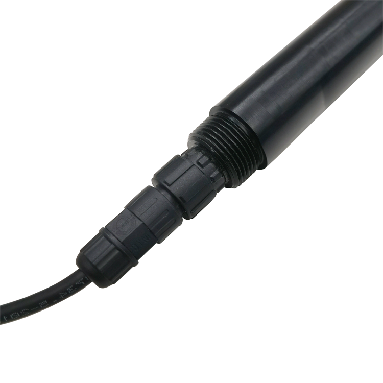
The cable connector pictured below is part of the electrical connection, not a process seal. Keep terminals and joints out of the liquid and provide strain relief. Do not use cable tension to hold the probe against process forces.
Review how the pipe fills, drains and behaves during startup. A point that is fully wetted at normal flow may collect air when a pump starts or the line empties. Locate the active region where the intended water contact can be maintained and inspect whether the assembly traps gas near the cap.
Do not prescribe an insertion direction without the actual holder drawing and instrument requirements. Mechanical access, pipe size and local flow can change the appropriate arrangement. Confirm the sensing position relative to the pipe wall, solids accumulation and any fitting that obstructs sample exchange.
In a bypass, use a route and chamber suitable for DO measurement and verify the actual flow. Keep the connection tight and avoid unnecessary residence time. Optical sensing does not consume oxygen, but it cannot preserve a sample whose oxygen concentration changes before reaching the cap.
Where concentration is very low, investigate whether the probe's stated accuracy and the sampling system can resolve the operating decision. A 0-20 mg/L industrial probe should not be presented as a trace-oxygen instrument simply because it displays two decimal places. Obtain a configuration and verification method suited to the required low-level duty.
Draw the removal route and identify which parts remain under pressure. Use the site's approved isolation, depressurisation and verification procedure before loosening a process connection. A standard immersion probe must not be treated as a hot-tap or live-retractable device unless an explicitly rated assembly provides that capability.
Provide a repeatable return position, correct seals and access to clean the sensing cap without scraping it. Follow the optical-cap replacement and verification procedure for the delivered instrument. A new cap is not a reason to change unrelated PLC scaling, and a wrong host value should not be corrected by arbitrary sensor calibration.
For a membrane-covered alternative, include membrane condition, electrolyte service and any required preparation in the maintenance plan. Compare access and actual staff capability rather than assuming one service interval fits every water matrix. Keep required spare parts identified by the correct instrument and sensing assembly.
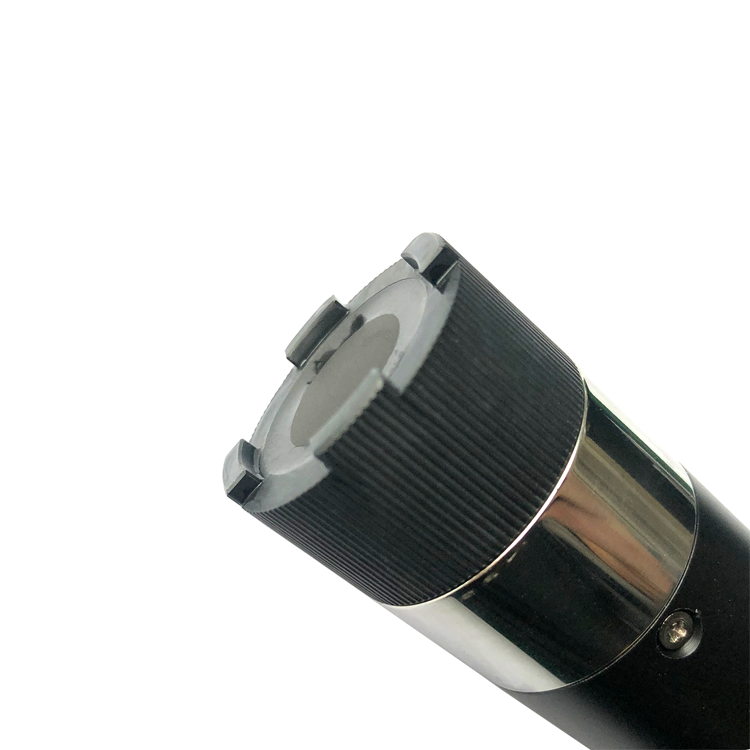
The cap shown below illustrates why the measuring end needs protection during removal. Avoid contact with hard fittings or deposits. Do not infer a cleaning brush or automatic cleaning capability from an enclosure or platform option.
Check the DO reading with a suitable reference procedure under equivalent water conditions, then compare the direct digital output with the controller. Retain temperature, units and the compensation settings relevant to the test. Configured salinity compensation is not a measured salinity channel.
With RS485 Modbus RTU, confirm the delivered address, serial settings, register definition and scaling. A PLC, RTU or data logger can acquire compatible data, while remote communications require a suitable gateway or network arrangement. Do not assume a basic probe provides relay outputs, a cloud connection or controller logic.
Test the indications for service, stopped sample flow where monitored, and loss of communication. A valid serial response from a stagnant bypass is a different condition from a failed connection. Agree how the receiving system identifies each case rather than turning all faults into a believable zero or a frozen last value.
No. It describes a mechanical connection, not the full pressure, sealing, retention and removal design. Confirm the proposed assembly and operating conditions before specifying direct pipe insertion.
Its measurement does not consume oxygen, unlike an amperometric membrane method. It still needs representative water at the cap. Stagnation, gas ingress, bubbles and sample alteration can make the installed value unsuitable.
It can improve access when correctly engineered, but it adds tubing, pressure changes and residence time. Assess how those features affect oxygen and verify the actual sampling conditions.
Only if the complete instrument and assembly are explicitly suitable for that cleaning condition. The NBL-WQ-DO operating range is 0-45 degrees C; do not infer high-temperature cleaning compatibility from IP68 or a metal housing section.
Provide normal and extreme pressure and temperature, pipe dimensions, water chemistry, expected DO band, cleaning conditions and the proposed holder or bypass drawing. Include the controller input and service isolation plan.
Not automatically. Their raw sensing signals and digital interfaces can differ. Check the exact transmitter input, supported probe identity and output protocol before retaining the existing electronics.
Not with an ordinary immersion installation. Live removal requires a specifically engineered and rated retractable system and its approved procedure. Do not loosen the probe based only on its thread or IP rating.
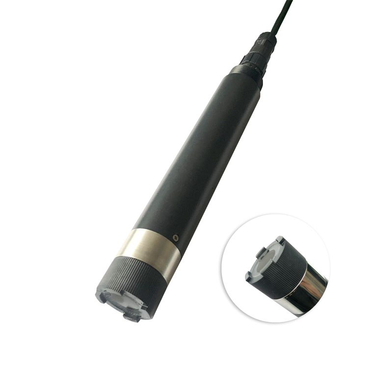
An inline dissolved oxygen sensor is a complete measurement installation, not only a choice between optical and membrane principles. Establish the required DO capability, preserve the sample and verify the pressure assembly and service method. NiuBoL can assess a fluorescence-probe configuration when the process conditions and mechanical arrangement are defined, without treating an immersion specification as blanket pipeline approval.
Prev:ORP Meter: Can an Inlet-to-Outlet Difference Verify Treatment?
Next:Digital Weather Station: Turn Farm Observations into Field Decisions
Related recommendations
Sensors & Weather Stations Catalog
 Agriculture Sensors and Weather Stations Catalog-NiuBoL.pdf
Weather Stations Catalog-NiuBoL.pdf
Agriculture Sensors Catalog-NiuBoL.pdf
Water Quality Sensor Catalog-NiuBoL.pdf
Related products
 Combined air temperature and relative humidity sensor
 TDR Soil Moisture & Temperature Sensor for irrigation| RS485 |4-20mA| NBL-S-THR
 Soil pH sensor RS485 soil Testing instrument soil ph meter for agriculture |NBL-S-PH
 Wind Speed sensor Output Modbus/RS485/Analog/0-5V/4-20mA
 Tipping bucket rain gauge for weather monitoring auto rainfall sensor RS485/Outdoor/stainless steel
 Pyranometer Solar Radiation Sensor 4-20mA/RS485


Screenshot, WhatsApp to identify the QR code
WhatsApp number:+8615367865107
(Click on WhatsApp to copy and add friends)

