

— Blogs —
—Products—
 Consumer hotline +8618073152920
WhatsApp:+8615367865107
Address:Room 102, District D, Houhu Industrial Park, Yuelu District, Changsha City, Hunan Province, China
Product knowledge
Time:2026-11-07 15:52:46 Popularity:5
A sensor converts a physical change — capacitance, conductivity, light intensity, displacement — into an electrical quantity, conditions and digitises it, then exposes it as an analogue loop or a digital register. The published accuracy describes only one part of that chain. The errors that dominate field data usually enter at the sensing element's contact with the medium, at the temperature compensation stage, or at the last step where a register value is scaled into engineering units.
Every sensor exploits a repeatable relationship. A capacitance probe uses the large difference in dielectric constant between water, soil solids and air. A conductivity cell measures current between electrodes at a known excitation and geometry. A silicon photovoltaic detector produces a current proportional to illuminance. A pH electrode develops a potential that varies with hydrogen ion activity. In each case the relationship is conditional: it holds for a stated geometry, temperature, excitation and medium.

Figure 1. Combined air temperature and relative humidity sensor.
That conditionality is why "range" and "accuracy" cannot be read in isolation. NiuBoL's soil EC sensor documentation gives a measurement range of 0–15 mS/cm with 0.01 mS/cm resolution, a salinity range of 0–8000 mg/L with 1 mg/L resolution, and a soil pH range of 0–14 pH. The EC channel includes temperature compensation over 0–50°C on the three-in-one NBL-S-TMC probe, because conductivity changes with temperature even when the dissolved salt content does not. Outside that compensation window, a conductivity number is not a compensated number and should be labelled as such.
Range selection is part of the error budget too. NiuBoL lists four measuring ranges for one level sensor family: 0–50 mm, 0–100 mm, 0–150 mm and 0–250 mm. Choosing the 0–250 mm variant for a tank that never exceeds 60 mm spends resolution unnecessarily. With a fixed digitization width, the smallest detectable change scales with the selected span.
| Parameter | Published value | What it actually constrains |
|---|---|---|
| Soil moisture range | 0–100 % | Measurement span, not plant-available water |
| Soil temperature range | −50 to 100 °C | Span of the temperature channel |
| Moisture resolution | 0.1 % | Smallest reported increment, not accuracy |
| Moisture accuracy | ±3 % | Absolute error under stated conditions |
| Temperature accuracy | ±0.5 °C | Error of the temperature channel |
| EC range / resolution | 0–15 mS/cm / 0.01 mS/cm | Span and smallest increment |
| Salinity range / resolution | 0–8000 mg/L / 1 mg/L | Derived channel, geometry-dependent |
| pH range | 0–14 pH | Electrode span |
| Supply | DC 12–24 V | Defines the acceptable bus supply at the device |
| Outputs | RS485 Modbus, 4–20 mA, 0–5 V | Integration options, each with different error behavior |
Note the difference between resolution and accuracy. A 0.1% resolution on a channel with ±3% accuracy means the last digit is far smaller than the uncertainty; displaying three decimals conveys precision the instrument does not have. Conversely, a coarse resolution on a narrow range can hide a real change that matters to a control loop.
The raw element signal is small and often nonlinear. Conditioning amplifies, filters and linearises it; compensation removes a known secondary dependence; an ADC converts it to a digital word. Each stage has its own failure mode.
Excitation stability. A conductivity cell's reading is proportional to the excitation and to the cell constant. Drift in either appears as a concentration change. This is why an EC channel is temperature compensated as standard on combined soil probes.
Amplifier zero and leakage. A small offset at the input becomes a fixed bias at low readings. On a picoampere-scale channel, moisture films on insulators create leakage paths that the amplifier cannot distinguish from signal. On industrial channels, ground loops and common-mode noise play the same role.
Filtering and response time. Filtering suppresses noise but delays response. A heavily smoothed channel can miss a wetting front, an alarm threshold crossing or a short emission spike. The response time should be specified at a stated step change, not quoted as an unqualified "fast".
ADC span and scaling. If the firmware maps 0–15 mS/cm to a 16-bit word, one count is 15/65535 ≈ 0.000229 mS/cm — finer than the published 0.01 mS/cm resolution, meaning the effective resolution is set by noise and the element, not by the ADC. Confusing ADC counts with instrument resolution is a common source of over-optimistic specification tables.
NiuBoL offers RS485 Modbus RTU, 4–20 mA and 0–5 V versions on several soil sensor families, and notes that the RS485 version supports integration into third-party monitoring systems and can connect to compatible data loggers, PLCs or IoT gateways, which then forward data to a cloud platform or private server. The choice is not just about wiring convenience.

Figure 2. Wind Speed sensor Output Modbus/RS485/Analog/0-5V/4-20mA.
RS485 Modbus RTU preserves the digital word, device address and diagnostics. Scaling is done once, in the logger, and can be audited by decoding a raw frame. Multiple devices share one bus. Its risks are bus topology, addressing, termination and the assumption that a passing poll implies a healthy analogue front end.
4–20 mA is robust over long runs and is natively understood by PLCs. The live zero makes an open circuit detectable (0 mA), but the loop hides internal diagnostics, and the receiving system's input resistor and scaling add their own error.
0–5 V suits short, laboratory-style wiring. It is the most vulnerable to voltage drop, ground offsets and induced noise, and should not be chosen for a long outdoor run.
A practical audit: log the raw digital word alongside the scaled engineering value for the first week. If the two ever disagree in a way that is not explained by a documented scale factor, the problem is in the integration layer, not the sensing element.
Consider the EC channel at 0–15 mS/cm with 0.01 mS/cm published resolution. A reading of 8.42 mS/cm therefore carries 842 reported increments. If the instrument's stated accuracy under reference conditions is, say, a percentage of full scale, the absolute uncertainty scales with 15 mS/cm, not with 8.42 — an important distinction when the measured value is small. At 1.00 mS/cm, a full-scale-based error band is fifteen times larger relative to the reading than it is at 15 mS/cm. Always state whether the error is of reading or of full scale.
Now connect that to the temperature compensation window. Suppose a probe in a heated greenhouse reports an EC increase from 4.00 to 4.60 mS/cm between 06:00 and 14:00 while soil temperature rises from 18°C to 34°C. Both temperatures lie within the 0–50°C compensation range, so a correctly compensated channel should not show a purely thermal rise of that size. A persistent 15% increase therefore points to real solute change, evaporation concentrating the solution, or a compensation fault — and the way to separate them is to log temperature alongside EC and repeat the comparison with the probe held at constant temperature in a wet, well-mixed sample.
The arithmetic is simple, but the conclusion depends entirely on knowing the compensation range and the error convention. Without those two pieces of metadata, the same dataset supports opposite interpretations.
Contact and geometry. A dielectric probe with an air gap reads the gap. A conductivity cell with fouled electrodes reads the fouling layer. No amount of digital filtering repairs a broken physical interface.
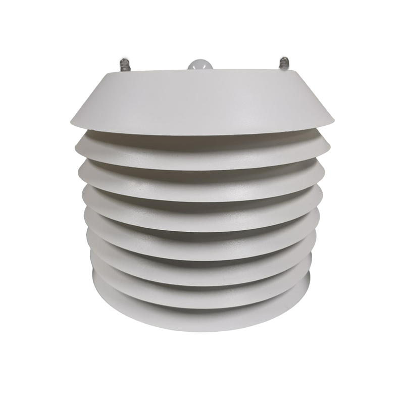
Figure 3. NiuBoL weather sensor assembly for checking multi-parameter channel assignment.
Temperature outside the compensation window. Compensation is specified over a range; outside it, the correction is either extrapolated or absent. Label the data accordingly.
Cross-sensitivity. A soil moisture reading responds to salinity; an EC reading responds to moisture because dissolved ions need a continuous water pathway. NiuBoL's documentation notes that above roughly 20% VWC the EC channel becomes more representative of soluble salt content, while cautioning that 20% is a measurement reference rather than a universal irrigation threshold. Channels that share a medium are not independent.
Supply and grounding. Under-voltage, ground loops and shield termination faults appear as drift, noise or dropouts. They are installation errors, not sensor errors.
Scaling and metadata loss. If a logger stores only a smoothed engineering value, later re-analysis cannot recover the raw word, the compensation state or the accuracy convention. Store the raw value and the metadata with it.
Before a specification table is copied into a tender or an article, five questions settle most later disputes.
One: is the accuracy of reading or of full scale? At 10% of a 0–15 mS/cm span, an error expressed as a percentage of full scale is ten times larger relative to the measured value than the same percentage of reading. Convert both to absolute units at your operating point.
Two: over what range does compensation apply? The combined soil probe documents EC temperature compensation over 0–50°C. Outside that window the number is uncompensated, and no downstream processing can recover the missing correction.
Three: is the resolution set by the digitiser or by noise? A 16-bit word across 0–15 mS/cm gives roughly 0.00023 mS/cm per count, far finer than the published 0.01 mS/cm resolution. The effective resolution is set by the element and the analogue front end, not by the ADC width.
Four: what does each output option hide? RS485 Modbus RTU preserves the raw word and device status; a 4–20 mA loop keeps the live zero but hides internal diagnostics; a 0–5 V run adds voltage-drop and ground-offset error. Naming the output is not the same as naming the error behavior.
Five: what is the calibration traceable to, and at what interval? Range, resolution and accuracy describe a new instrument under reference conditions. A field instrument needs a documented zero/span procedure and a drift history. Ask for the reference conditions, the recommended re-check trigger and whether raw and compensated values can both be read.
A sixth, practical question belongs in the same list: which values can be logged. If the device exposes only a smoothed engineering value, a later re-analysis cannot recover the raw word, the compensation state or the accuracy convention. Store all three, plus the datasheet revision, with the site record.
Q1. What is the difference between resolution and accuracy?
Resolution is the smallest reported increment; accuracy is the uncertainty under stated conditions. A 0.1% resolution on a ±3% channel does not make the reading accurate to 0.1%.
Q2. Why is my EC reading rising when nothing changed?
Check temperature against the compensation range, electrode fouling, and moisture — EC depends on a continuous conductive water pathway, so a drying soil concentrates the remaining salts.
Q3. Which output preserves the most diagnostic information?
RS485 Modbus RTU, because it carries the raw word, address and device status. Analogue loops hide internal diagnostics.
Q4. Does a wider measuring range cost me anything?
Usually yes: with a fixed digitiser, the smallest detectable change scales with the span. Select the narrowest range that covers the real process.
Q5. Can I compare accuracy figures quoted as % of reading and % of full scale?
Only after converting both to the same concentration. The two conventions give different absolute errors away from full scale.
Q6. Should I log the raw register value?
Yes. The raw word plus temperature, supply status and datasheet revision is what makes a dataset auditable months later.
Prev:Installing a Monitoring System: Siting, Wiring, Commissioning and the Mistakes That Bias Data
Next:Choosing a Monitoring Station: Specs, Siting and Total Cost of Ownership
Related recommendations
Sensors & Weather Stations Catalog
 Agriculture Sensors and Weather Stations Catalog-NiuBoL.pdf
Weather Stations Catalog-NiuBoL.pdf
Agriculture Sensors Catalog-NiuBoL.pdf
Water Quality Sensor Catalog-NiuBoL.pdf
Related products
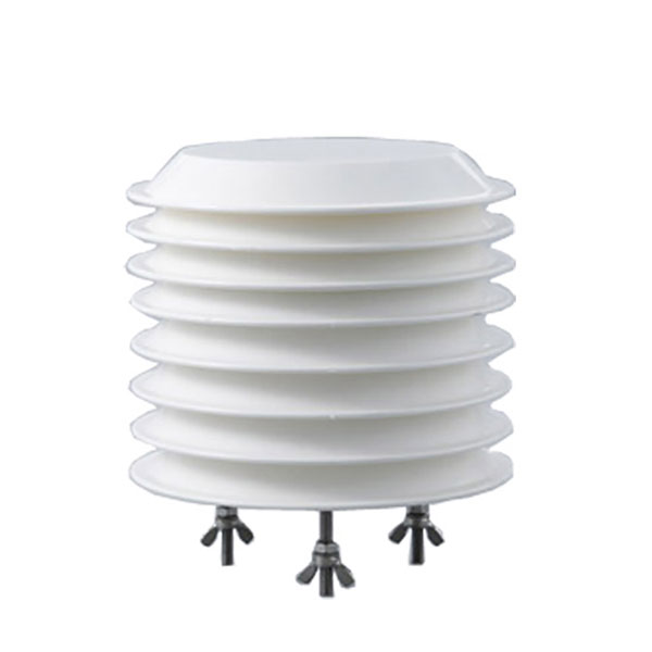 Combined air temperature and relative humidity sensor
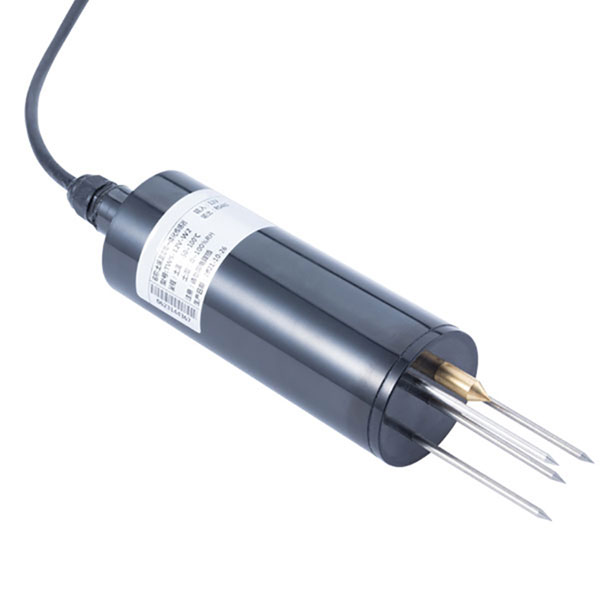 TDR Soil Moisture & Temperature Sensor for irrigation| RS485 |4-20mA| NBL-S-THR
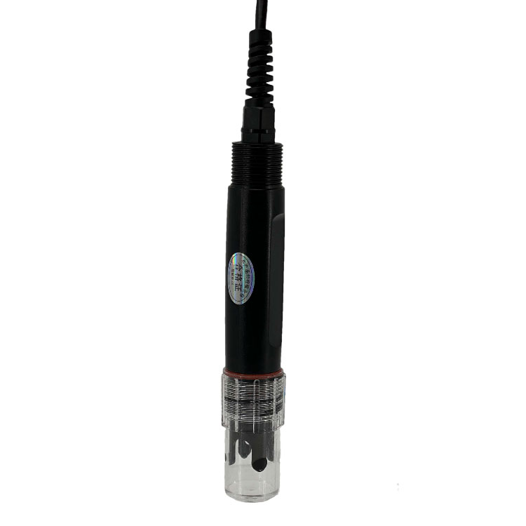 Soil pH sensor RS485 soil Testing instrument soil ph meter for agriculture |NBL-S-PH
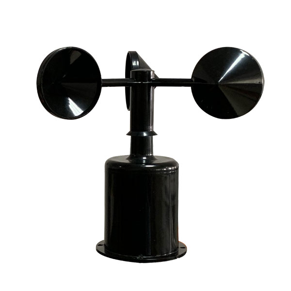 Wind Speed sensor Output Modbus/RS485/Analog/0-5V/4-20mA
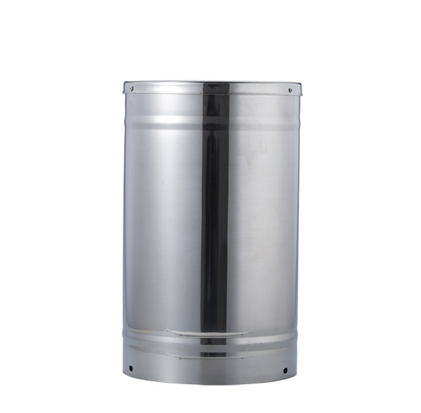 Tipping bucket rain gauge for weather monitoring auto rainfall sensor RS485/Outdoor/stainless steel
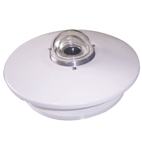 Pyranometer Solar Radiation Sensor 4-20mA/RS485


Screenshot, WhatsApp to identify the QR code
WhatsApp number:+8615367865107
(Click on WhatsApp to copy and add friends)