





— Blogs —
—Products—
 Consumer hotline +8618073152920
WhatsApp:+8615367865107
Address:Room 102, District D, Houhu Industrial Park, Yuelu District, Changsha City, Hunan Province, China
Product knowledge
Time:2026-09-07 16:27:33 Popularity:311
IoT monitoring system architecture separates four jobs: sensors measure, data loggers acquire and record, gateways connect networks, and platforms store and present information for users. One device may perform several jobs, but none should be assumed from its name. Before choosing hardware, decide where sensor values are decoded, where records survive an outage and where any control action executes. These decisions determine whether the system needs a separate gateway, a combined logger or additional local control equipment.
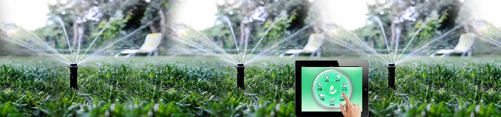
Consider a soil sensor connected to an irrigation monitoring station. The probe measures conditions around its electrodes and provides a signal. An acquisition device reads that signal, applies the correct scale and associates it with a time and measurement point. A network connection carries the record to a server, where software stores it and makes it available on a chart or alarm screen.
Each handoff can be working or faulty independently. The probe can be healthy while the network is unavailable. The server can receive messages while applying the wrong unit. A chart can show yesterday's value even though the current acquisition process has stopped. A useful architecture makes those states distinguishable rather than displaying one general online indicator.
| Layer | Primary job | Capability that must not be assumed |
|---|---|---|
| Sensor | Measure a physical quantity and output a defined signal | Cellular access, GPS, long-term storage or a cloud account |
| Data logger or acquisition controller | Read inputs, decode measurements and create records | Permanent storage, automatic retransmission or valve-control logic |
| Gateway or network device | Connect a field system to another network or protocol | Understanding every sensor register or retaining a measurement archive |
| Monitoring platform | Store, display and process received records | Knowledge of events that were never acquired or transmitted |
The names on a quotation are less important than this division of work. A product sold as an RTU may include acquisition, storage and communications. Another device sold as a gateway may only forward serial bytes. Ask which functions are configured and test them with an actual sensor record.
An RS485 sensor provides a serial interface. When it uses Modbus RTU, the receiving device must send the appropriate request and decode the response. The protocol does not automatically identify whether a register contains temperature, conductivity or rainfall, and it does not supply the site's channel names.
Analog measurements need an acquisition input matched to the signal. For example, a 4-20 mA transmitter requires a suitable current-input arrangement and the correct engineering scale. A voltage input configured for 0-5 V cannot be assumed to accept that current directly. A pulse-output rain gauge needs event counting, which differs from periodically reading a slowly changing analog value.
The logger turns these inputs into useful measurements. It can apply calibration coefficients, calculate interval statistics and record quality flags where the software supports them. These functions should have one clear owner. Applying the same scale in both the logger and platform can create an error even though every connection is functioning.
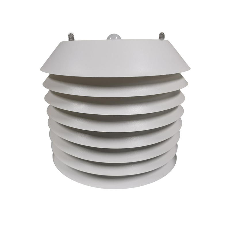
The weather station configuration brings these components together with mounting and power. A compact weather sensor assembly still needs an acquisition and communication arrangement unless those functions are explicitly built into the selected version. The sensor housing shown below should not be mistaken for a complete cloud-connected station.
If an existing PLC or data logger already produces correctly scaled records, a network gateway may be sufficient to connect that equipment to the required server. Adding another logger can duplicate polling and create two different timestamp or scaling conventions. Keep the existing acquisition role where it already meets the project requirements.
If the site has only sensors, a serial-to-network converter may not be enough. Something must schedule reads, interpret values and decide what to retain. That work can run in a configured edge device or, for suitable architectures, on a remote host. The latter arrangement makes measurement availability more dependent on the network unless local acquisition is also provided.
A combined logger and gateway reduces the number of physical devices and interconnecting cables. It can also make one failed unit affect both acquisition and transmission. Separate devices allow the local logger to keep operating while a modem is serviced, provided power and storage are independent enough to support that behavior.
For a small unattended weather station, a combined device may simplify installation. For a plant that already has a controller and historian, retaining those systems and adding only the missing communication function may be more practical. The choice follows the existing equipment and required outage behavior, not a rule that every project needs four separate boxes.
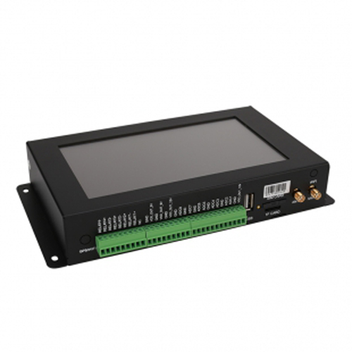
The TG462 and TG462S data loggers combine acquisition interfaces with networking and storage hardware. The TG462S adds a local touchscreen. These capabilities can support a multi-sensor station, but the application software still determines how channels are decoded, stored and forwarded.
| Hardware provision | TG462 / TG462S | Architecture decision |
|---|---|---|
| RS485 interfaces | 3 ports | Allocate compatible sensor groups and identify the polling master for each segment |
| Analog acquisition | 8 channels, 12-bit ADC | Select supported current or voltage conditioning; ADC resolution is not complete system accuracy |
| Digital interfaces | 4 DI and 4 relay outputs | Confirm event-counting requirements and external load interfaces before assigning functions |
| Local storage hardware | Micro SD support up to 32 GB; internal flash varies by version | Define which storage holds measurements and how records are exported or recovered |
| Ethernet | 2 RJ45 ports | Plan the connection to the local network or server; cellular configuration is a separate choice |
| Supply and environment | 5-35 VDC; -35 to 75 C; IP30 | Install inside a suitable field enclosure rather than exposing the unit directly to rain |
| Location and display | Optional GPS; TG462S has a 7-inch display | Order these functions when needed and define how their information is recorded |
A memory-card slot does not by itself guarantee uninterrupted historical records. Record capacity depends on the application, allocated space and file format. Retention after a power interruption, automatic recovery and export behavior are software functions that need verification.
Similarly, a relay output does not establish that the station can operate a pump or valve directly. The electrical load, isolation, actuator supply, feedback and local logic must be designed for that duty. Monitoring capability and control capability should be described separately even when they share the same enclosure.
For a fixed station, surveyed coordinates can be stored with the station identity. Repeated GPS measurements may add little value if the installation never moves. A mobile station has a different need: position should be associated with the measurement time, and the system should identify invalid or stale location data. A GPS option is not automatically a heading or vehicle-motion compensation system.
Historical data can exist at the logger, the server or both. Local records help investigate network interruptions and field faults. Server records support multi-site access and longer-term analysis. Decide which copy is authoritative for corrections, and whether a technician can retrieve the local history without the original cloud service.
An alarm also has a location. A platform-only alarm depends on communication and server operation. A local alarm can continue during a network interruption if its inputs, power and logic remain available. For irrigation, specify whether loss of communication stops watering, permits a local schedule or requires manual intervention. There is no universally correct failure response for every crop and hydraulic system.
Keep the time of measurement distinct from the time of upload. A delayed record can be valid historical data without describing the current field condition. The operator should be able to tell whether the latest visible measurement is fresh, delayed or missing before acting on it.
If the sensor value is absent locally, investigate the instrument, its power and the acquisition input. If a local engineering value exists but no local record is saved, investigate the logging application and storage. If local records exist but are missing remotely, move to the network, server connection and ingestion process.
If the server contains a correct record but the chart is wrong, inspect the dashboard's channel mapping, unit conversion and time filter. This sequence avoids replacing a functioning soil probe because a database field was renamed or an old chart was cached.
Test the architecture in stages with one real measurement channel. Establish the local reading, confirm a stored record and locate that same record remotely. Then perform a controlled network interruption and a separate power restart. Observe which functions continue and which recover. Do not treat a successful reconnect as proof that every missing measurement has been restored.
A customer-owned platform can often remain in place when sensors or loggers change, provided the new equipment meets its data and connection requirements. Define the measurement identifiers, units, timestamps and supported ingestion method before selecting the communication configuration. A proprietary application account should not be assumed necessary for every installation.
For a quotation, give NiuBoL the existing controller and server details, the required sensor channels and the functions that must continue without internet access. State whether the project is monitoring only or also controlling equipment. This allows the missing equipment and configuration work to be identified without duplicating hardware that the site already owns.
RS485 is a field communication interface, not an internet connection. A separate or integrated device must read the measurements and communicate with the server. Only a sensor explicitly equipped with the required networking and application functions can perform both roles itself.
Yes. Combined hardware is common, but verify acquisition, persistent recording and network forwarding as separate functions. A gateway label alone does not establish that the device stores historical measurements.
Place it where the system can obtain a valid position and associate it with the relevant measurement time. Fixed sites may use configured coordinates; mobile systems need a suitable live position source. The GPS receiver need not be inside every sensor.
No. The application must store records, retain them for the required period and implement the required retrieval or forwarding behavior. Test that sequence with a controlled outage rather than relying on the advertised card capacity.
Decisions that must continue without connectivity need suitable local logic and safeguards. Cloud analysis can inform schedules and reporting, but the behavior during lost communication must be chosen for the actual irrigation system.
Clarify account ownership, user permissions, data export, retention and any recurring service requirements. Hardware connectivity does not establish access rights or long-term availability of a hosted application.
Possibly, if the remaining interfaces, power and software support the additional sensors. Check channel processing and storage demands as well as spare terminals. Adding a different protocol may require a new driver or interface, not just another cable.
A useful IoT monitoring system architecture assigns each function to specific equipment or software. Identify who measures, who records, who transmits and who acts on the result. NiuBoL sensors and configured acquisition equipment can then be selected around those responsibilities, with outage behavior and access to historical data established before commissioning.
Prev:Solar Power for Weather Stations: Panels, Batteries and Autonomy
Next:Data Logger Selection: Interfaces, Storage, GPS, 4G and Protocols
Related recommendations
Sensors & Weather Stations Catalog
 Agriculture Sensors and Weather Stations Catalog-NiuBoL.pdf
Weather Stations Catalog-NiuBoL.pdf
Agriculture Sensors Catalog-NiuBoL.pdf
Water Quality Sensor Catalog-NiuBoL.pdf
Related products
 Combined air temperature and relative humidity sensor
 TDR Soil Moisture & Temperature Sensor for irrigation| RS485 |4-20mA| NBL-S-THR
 Soil pH sensor RS485 soil Testing instrument soil ph meter for agriculture |NBL-S-PH
 Wind Speed sensor Output Modbus/RS485/Analog/0-5V/4-20mA
 Tipping bucket rain gauge for weather monitoring auto rainfall sensor RS485/Outdoor/stainless steel
 Pyranometer Solar Radiation Sensor 4-20mA/RS485


Screenshot, WhatsApp to identify the QR code
WhatsApp number:+8615367865107
(Click on WhatsApp to copy and add friends)

