

— Blogs —
—Products—
 Consumer hotline +8618073152920
WhatsApp:+8615367865107
Address:Room 102, District D, Houhu Industrial Park, Yuelu District, Changsha City, Hunan Province, China
Product knowledge
Time:2026-08-04 08:47:04 Popularity:257
A wastewater online sensor cabinet needs a model-specific power schedule, a defined RS485 layout and enough access to isolate and service one branch without confusing the others. Design from the actual connected devices and field routes. Sensor IP68 ratings, a shared Modbus protocol and spare DIN-rail space do not by themselves establish a suitable completed cabinet.
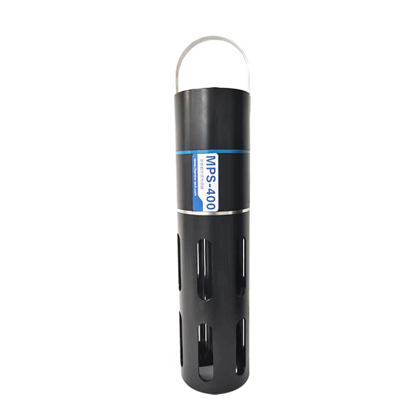
Do not wait until the probes arrive to decide cable entry, DC rails and terminal locations. Each measuring point needs an identity that follows it from the tank or sample line to the cabinet terminal and the host channel. Record the exact model and version, not only labels such as pH or COD.
| Drawing or schedule | Information that makes it usable |
|---|---|
| Device and load schedule | Supply limits, running and event loads, required output and which devices share a feed |
| Terminal schedule | Field point, cable identification, power polarity, communication pair and any analog connections |
| Bus layout | Physical trunk and branches, termination locations, serial settings and device addresses |
| Panel arrangement | Protection, power conversion, RTU or PLC, field terminals, cable ducts and removal access |
| Environmental design | Site exposure, temperature, moisture, chemical atmosphere, entry sealing and required approvals |
A device address is not a physical terminal number. Keep both on the drawing so a technician can disconnect the intended point without guessing. If two ranges or versions of a sensor are possible, resolve the order configuration before assigning the final input span or register interpretation.
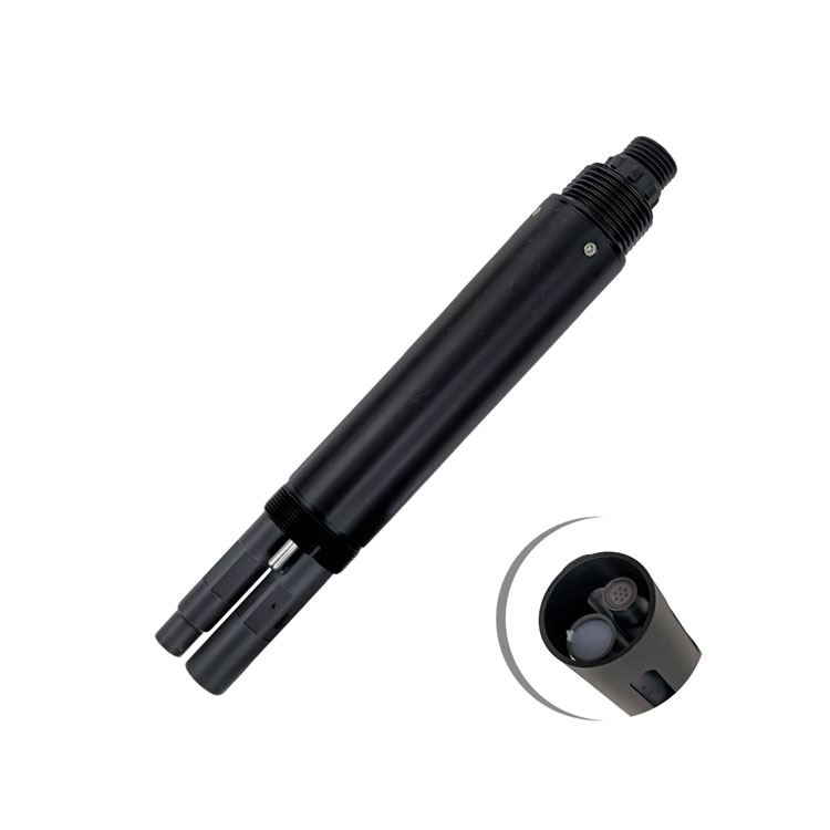
The NiuBoL MPS-5B integrated probe requires 12 V DC. It must not be placed on a 24 V rail simply because separate water-quality probes accept 12-24 V. A cabinet can need separate regulated branches or appropriate conversion even when every sensor uses RS485 Modbus RTU.
| Identified device | Supply and stated consumption |
|---|---|
| NBL-WQ-MPS-5B | 12 V DC; 2 W at 12 V |
| NBL-WQ-MPS-5A, if selected instead | 12 V DC +/-5%; 5 W at 12 V |
| NBL-WQ-COD | 12-24 V DC; 0.3 W at 12 V |
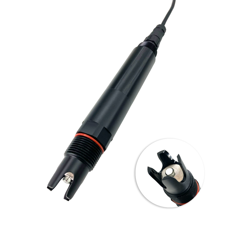
| NBL-WQ-PH | 12-24 V DC; 0.2 W at 12 V |
For illustration, one MPS-5B plus one NBL-WQ-COD totals 2.3 W at the stated operating points, approximately 0.192 A at 12 V. That is not a power-supply selection: the logger, gateway, conversion loss, cleaning or startup demand and environmental equipment remain to be assessed. Use the selected devices' event loads and the supply's temperature derating when sizing the completed panel.
The COD probe also needs the correct version-specific output. A digital-only configuration cannot supply an analog loop just because a different product family offers 4-20 mA.
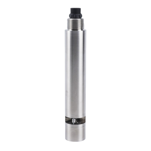
Provide clearly identified power branches and protection appropriate to the load, conductors and installation. Consider what remains powered when a probe branch is isolated, and whether a common converter failure removes every measurement. Protection and electrical isolation are different functions; select them deliberately rather than treating a terminal block as either.
Locate test points where qualified personnel can verify the relevant DC output without disturbing adjacent conductors. Check field-end voltage under the relevant loads, not only the unloaded cabinet supply. For detailed route and voltage-loss diagnosis, use the water quality sensor cable checks.
For a separate ammonium measurement point, keep the power, communication and parameter identity associated with that point. Do not change electrode calibration to compensate for a cabinet power fault or a receiving-system scale error.
A group of cables entering a cabinet does not define a correct bus. Show the trunk and short device branches, and identify any repeater or isolated segment. An uncontrolled star at the terminal strip can create a different electrical network from the intended field drawing.
Document where termination and biasing are provided, including any built into the host. Avoid adding termination at every sensor. Confirm the signal reference, shielding, grounding and isolation requirements for the selected interfaces; there is no universal shield instruction for every mixed installation.
Use unique addresses and compatible serial settings, then document each model's register mapping, data type, scale and unit. The number of usable sensors depends on electrical loading, route, timing, host capability and required update time. A protocol address space is not a guarantee that the same number of probes can be connected in a working field network.
During expansion, test the complete bus again. A new point can change load, cable geometry or scan time even if its individual bench test passes. Where a parameter must continue during maintenance, consider segmentation rather than relying on a single shared path for all critical channels.
Use the actual device and connector dimensions to check cable bend radius, terminal access and component removal. Leave enough clearance to replace a power supply or surge device without pulling unrelated sensor conductors. The necessary space depends on the components; a fixed generic gap is not a substitute for a layout check.
Labels should remain visible after ducts are closed. Check that a cable gland grips the cable jacket correctly and that the door can close without compressing a service loop. Reserve expansion space for a defined additional load and cable route, not merely an empty rectangle on a drawing.
A pH measuring point still needs safe probe retrieval and calibration access outside the cabinet. Electrical terminals inside the box do not make an inaccessible sensor maintainable. If sample conditioning is included, separate wet service work and drainage from exposed electrical equipment.
Select the completed enclosure for rain, washdown, dust and condensation exposure, including glands, doors and any added ventilation. The immersed probe's IP rating does not apply to the cabinet. Chemical corrosion and a hazardous-area classification also require their own assessment; an IP label is not an explosion-protection approval.
Assess internal temperature with the expected loads and door closed. Solar gain, power conversion and any heater change the thermal conditions. Ventilation or cooling must suit the site and preserve the required protection. A tightly sealed cabinet can still develop condensation during temperature changes.
Electrical safety, bonding, circuit protection and any hazardous-area equipment selection need competent design under the applicable site requirements. Do not place an ordinary monitoring cabinet in a classified location without the required assessment and suitable equipment.
Verify every configured point on the final wiring with the actual host scan and timeout settings. Exercise cleaning cycles and representative communication loads. Confirm that one disconnected probe creates the intended fault indication and that the host does not present an old value as a fresh observation.
Compare raw or decoded device values with PLC or RTU values and then with the remote display. Test the intended behavior during an uplink interruption, including local storage and retransmission only where supported. Repeat the operating check with covers and doors in their normal closed positions.
A DO channel should keep its measurement and fault status distinct. Loss of that sensor must not be displayed as zero oxygen or used as an automatic process command unless the control design explicitly defines a safe, validated response.
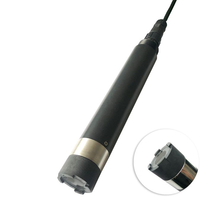
Only if the completed power arrangement delivers an acceptable voltage to every device. MPS-5B requires 12 V; other probes may accept 12-24 V. Use the actual load schedule and any required conversion rather than a family-wide assumption.
Define the intended future device, protection, terminals and cable entry, then check their dimensions and service access. An arbitrary percentage of spare rail does not confirm that expansion can be wired or maintained.
No. Serial settings, addresses, register definitions and units still need to match. Test the delivered versions on the intended host before treating them as an accepted group.
Only within a design that controls leakage, drainage, electrical separation and service access. A wet maintenance task must not expose energized equipment or compromise the required enclosure protection.
Send the device schedule, current and future point count, power source, field routes, host equipment, environmental exposure and required alarms. Identify what is supplied as a complete cabinet and what remains with the site integrator.
For an immersed turbidity point, carry the same point identifier through its probe cable, cabinet terminals and displayed channel. That continuity makes a physical isolation test useful instead of creating uncertainty about which sensor was disconnected.
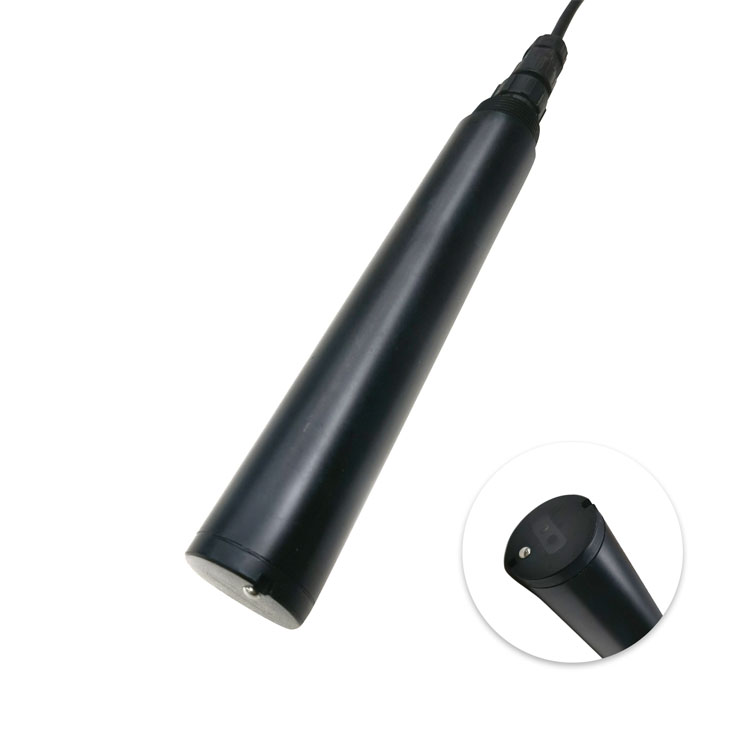
A wastewater online sensor cabinet is ready for service when the power rails match the connected models, the drawn bus matches the wiring, and individual faults can be isolated without guesswork. Check closed-door operation and real removal access before delivery. Keep enclosure suitability separate from the ratings of the field probes.
Prev:Water Quality Monitoring Buoy Sensor Package: Seasonal Data Checks
Next:Online Water Quality Sensor Replacement: Diagnose Before Ordering
Related recommendations
Sensors & Weather Stations Catalog
 Agriculture Sensors and Weather Stations Catalog-NiuBoL.pdf
Weather Stations Catalog-NiuBoL.pdf
Agriculture Sensors Catalog-NiuBoL.pdf
Water Quality Sensor Catalog-NiuBoL.pdf
Related products
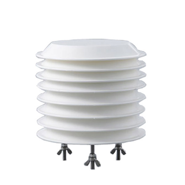 Combined air temperature and relative humidity sensor
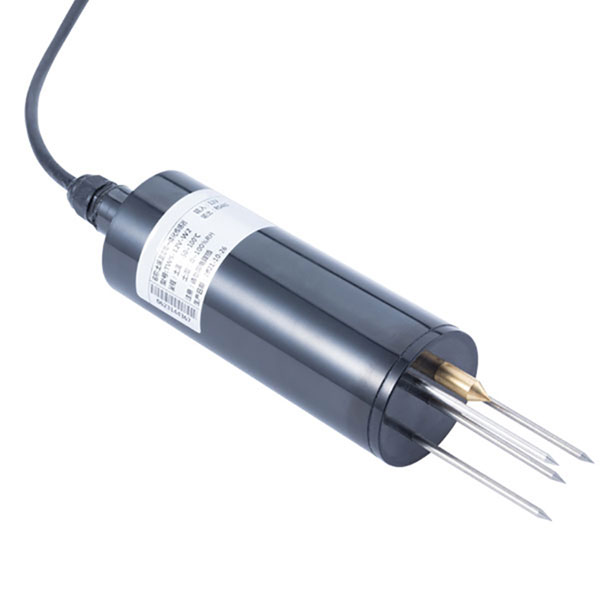 TDR Soil Moisture & Temperature Sensor for irrigation| RS485 |4-20mA| NBL-S-THR
 Soil pH sensor RS485 soil Testing instrument soil ph meter for agriculture |NBL-S-PH
 Wind Speed sensor Output Modbus/RS485/Analog/0-5V/4-20mA
 Tipping bucket rain gauge for weather monitoring auto rainfall sensor RS485/Outdoor/stainless steel
 Pyranometer Solar Radiation Sensor 4-20mA/RS485


Screenshot, WhatsApp to identify the QR code
WhatsApp number:+8615367865107
(Click on WhatsApp to copy and add friends)