





— Blogs —
—Products—
 Consumer hotline +8618073152920
WhatsApp:+8615367865107
Address:Room 102, District D, Houhu Industrial Park, Yuelu District, Changsha City, Hunan Province, China
Technical Support
Time:2026-09-07 16:27:29 Popularity:319
Multiple RS485 sensors can share one bus, but adding devices consumes both power capacity and polling time. Calculate the voltage available at remote sensors and the scan time with an unresponsive device before expanding a segment. Unique addresses and compatible serial settings are essential starting conditions, not proof that the proposed sensor count will work.
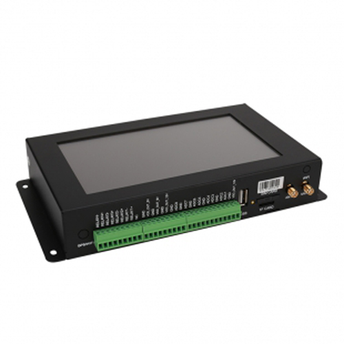
A shared bus reduces the number of serial ports required in a PLC, RTU or data logger. It does not make every RS485 instrument interchangeable. RS485 describes the electrical interface; the device must also use the protocol, baud rate and frame format expected by the client. An instrument using a proprietary serial message cannot be treated as a Modbus sensor simply because its terminals are marked A and B.
For a conventional two-wire Modbus RTU segment, use one client to request data from the addressed sensors. A maintenance computer must not poll the same segment independently while the operating controller is polling. Give the computer temporary control during an isolated test, or read data through the controller's supported upstream interface.
| Check before sharing a bus | Required decision | Consequence if missed |
|---|---|---|
| Protocol and serial format | Compatible Modbus RTU operation with matching baud rate, parity and stop bits | Devices may remain silent even with correct wiring |
| Device address | One unique supported address per sensor on the segment | Overlapping replies can corrupt otherwise valid messages |
| Register interpretation | A separate map, scale and unit for each model | A valid response can produce the wrong engineering value |
| Electrical loading and route | Check transceivers, cable, branches and termination together | The last added device may expose a marginal bus |
| Supply and timing | Calculate remote voltage and the full polling cycle | Resetting sensors or long data gaps can resemble communication faults |
Two new sensors can arrive with the same factory address. Connect each one separately on the bench, read a known register, change its address using the correct model-specific procedure, and read it again at the new address. Label the cable with that address and its intended location before connecting the next device. Test that the setting persists through a controlled power restart.
Standard Modbus serial individual addresses are 1 through 247; address 0 is reserved for broadcast transactions and is not an ordinary polled measurement address. A configuration tool may display a wider numeric range or offer a vendor-specific discovery command. Do not assume those options are suitable for normal shared-bus operation. Avoid configuration broadcasts with several uncommissioned devices connected.
Register numbers do not have to be unique across sensors. Devices 11 and 12 can both expose register 0 because the device address selects the instrument first. In the logger, keep both parts of the identity: serial port plus device address. If two separate ports each contain address 11, the cloud point names still need to distinguish them.
A replacement sensor is another common source of collisions. Before connecting a spare, compare its address, serial format and register revision with the removed unit. Keep the failed unit disconnected while testing the replacement at the same address. Renaming a dashboard tag does not change a device's Modbus address.
The original cable layout matters more than the appearance of the terminal box. Route a main twisted-pair trunk past the instruments and keep device stubs short. A terminal block can make wiring accessible, but it does not turn several long star branches into a properly engineered bus. For widely separated groups, separate ports or suitable isolated repeaters may be more practical than forcing all instruments onto one segment.
Place the required line termination at the two physical ends of the trunk, following the cable and transceiver design. Check for built-in termination before adding external resistors. Enabling termination at every sensor can overload the driver. Biasing, where required, is a separate function that establishes an idle state; do not add bias networks at arbitrary junctions.
Provide the signal-reference and protective-earth arrangement required by the equipment. A shield is not a substitute for a power return or a signal reference. Where instruments use separate supplies, evaluate ground-potential differences and isolation before bonding terminals. Outdoor routes also need appropriate surge protection and protected joints; those measures do not correct duplicate addresses or a faulty polling program.
Document the real route length and branch lengths, not just the straight-line distance on a site plan. There is no single maximum-distance claim that applies to every baud rate, cable and loading condition. If a distant sensor works on a short bench cable but not in the field, examine the installed segment before changing its measurement calibration.
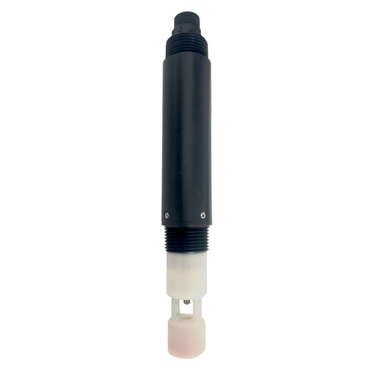
Communication uses a differential pair, but each sensor still needs power. Add the loads using their specified operating and startup conditions, including devices powered through the same cable. Then calculate voltage drop in the supply and return conductors. The voltage measured at the cabinet is not the voltage available at a remote probe during startup or cleaning.
For example, assume a 200 m one-way power run with a conductor resistance of 0.035 ohm/m and a hypothetical 0.10 A load concentrated at the far end. The loop resistance is 2 x 200 x 0.035 = 14 ohms; the drop is 1.4 V. A 12 V source would supply approximately 10.6 V at that load, before connector losses. Distributed loads require a section-by-section calculation because upstream cable sections carry more current.
The NiuBoL NBL-WQ-EC-S salinity sensor, for example, uses a 12-24 VDC supply and RS485 Modbus RTU output. Its typical 0.2 W consumption at 12 V is not a power specification for every water-quality sensor on the bus. Check each model, particularly instruments with cleaning motors or other intermittent loads. Select a supply and cable arrangement that keeps every instrument within its allowed input range.
Do not connect two independent power supplies together simply because their sensors share A/B. Keep power distribution intentional, with suitable circuit protection and the required reference or isolation arrangement. When testing a suspected voltage problem, measure at the affected device under load, including the period in which the fault occurs.
The client must finish or time out one request before starting the next transaction on the same segment. Sensor measurement rate, serial response time and dashboard refresh rate are different quantities. Reading a slowly updated measurement more frequently may only return the same stored value and consume bandwidth needed by other devices.
Start with the minimum request spacing and response behavior of the slowest relevant model, then measure complete transaction times. Read contiguous registers together only when the sensor supports that block. A single multi-parameter instrument can return several channels in one request; separate instruments cannot be combined into one ordinary addressed read.
| Hypothetical polling case | Calculation | Design meaning |
|---|---|---|
| 12 healthy sensors; 0.20 s allotted to each successful transaction | 12 x 0.20 = 2.4 s | Minimum estimated cycle under these assumptions, excluding extra scheduler overhead |
| One missing sensor; 1 s timeout with two retries | 3 attempts x 1 = 3 s | The absent device alone occupies three seconds |
| 11 healthy devices plus that missing sensor | 11 x 0.20 + 3 = 5.2 s | Faulted cycle is substantially longer than the healthy cycle |
These are planning examples, not NiuBoL response-time specifications. Set a bounded retry count and reduce the polling frequency of a persistently missing device so it does not monopolize the segment. Retain the last good value only with its original timestamp and a stale-data flag. Substituting zero for a timeout can create false low-moisture, low-level or low-salinity events.
If all readings fail after one addition, inspect that connection for a short, reversed conductors, duplicate address or extra termination. If only the distant devices fail under load, investigate supply drop and the long cable segment. If responses pass the CRC check but values are implausible, compare the register map and scaling before touching the wiring.
For a NiuBoL multi-sensor quotation, provide the sensor list, cable-route sketch, individual supply requirements and required update interval. This lets the serial-port count and power arrangement follow the actual installation. A short local tank installation and a dispersed field network should not automatically receive the same single-bus design.
No. It describes standard individual addressing, not guaranteed electrical capacity. Transceiver loading, cable design, power distribution and acceptable polling time can impose a lower limit. Obtain the supported segment design for the proposed instruments instead of buying solely against an address count.
Not necessarily. More current capacity does not remove resistance in a long cable. Measure the voltage under load and calculate the cable drop. A larger conductor, a different distribution arrangement or a permitted higher supply voltage may be appropriate, but every connected device must remain within its input limits.
No. A splitter provides connections but does not regenerate the signal, isolate segments or increase the driver's electrical capacity. An active repeater can serve a different purpose, but its isolation, timing and termination requirements must fit the system.
Not necessarily. Assign intervals according to measurement update rate and application need, while maintaining one coordinated request scheduler. A slow water-quality channel need not consume the same polling frequency as a faster-changing channel, provided timestamps and stale limits remain clear.
Consider separate segments when cable routes, incompatible serial settings, electrical loading or the worst-case polling cycle cannot meet the requirement on one bus. Splitting ports can also limit the effect of a cable fault. Check that the logger can schedule the ports as needed; a second connector alone does not prove independent acquisition.
A working bus with multiple RS485 sensors needs more than matching terminals. Establish unique addresses, compatible serial settings, a deliberate trunk layout and adequate remote power. Then test the polling cycle with a failed device as well as with all sensors responding. Those checks determine whether the installation can deliver the required measurements reliably.
Prev:How to Connect RS485 Sensors to PLCs, RTUs, Arduino and ESP32
Next:RS485 Sensor to Cloud: LoRaWAN, MQTT and HTTP Integration
Related recommendations
Sensors & Weather Stations Catalog
 Agriculture Sensors and Weather Stations Catalog-NiuBoL.pdf
Weather Stations Catalog-NiuBoL.pdf
Agriculture Sensors Catalog-NiuBoL.pdf
Water Quality Sensor Catalog-NiuBoL.pdf
Related products
 Combined air temperature and relative humidity sensor
 TDR Soil Moisture & Temperature Sensor for irrigation| RS485 |4-20mA| NBL-S-THR
 Soil pH sensor RS485 soil Testing instrument soil ph meter for agriculture |NBL-S-PH
 Wind Speed sensor Output Modbus/RS485/Analog/0-5V/4-20mA
 Tipping bucket rain gauge for weather monitoring auto rainfall sensor RS485/Outdoor/stainless steel
 Pyranometer Solar Radiation Sensor 4-20mA/RS485


Screenshot, WhatsApp to identify the QR code
WhatsApp number:+8615367865107
(Click on WhatsApp to copy and add friends)

