

— Blogs —
—Products—
 Consumer hotline +8618073152920
 WhatsApp:+8615367865107
Address:Room 102, District D, Houhu Industrial Park, Yuelu District, Changsha City, Hunan Province, China
Technical Support
Time:2026-09-07 16:27:28 Popularity:335
To connect RS485 sensors to PLCs, RTUs, Arduino or ESP32, first provide the correct physical interface and sensor power, then configure a Modbus RTU client to read the model's registers. A PLC with a compatible RS485 port may connect directly at the bus level. A microcontroller UART normally needs an external RS485 transceiver with compatible logic voltage and transmit-direction control.
Connecting an RS485 sensor involves reliable differential signaling and correct interpretation of the returned data. The host changes how those tasks are implemented. A serial connector, an analog input and an Ethernet socket are not substitutes for one another, even when all belong to the same controller.
| Available host interface | Hardware path | Software requirement |
|---|---|---|
| PLC or RTU with RS485 | Compatible bus terminals and correctly powered sensor | Modbus RTU client/master function configured for the sensor |
| PLC with Ethernet only | Compatible serial gateway if the sensor remains RS485 | Supported Ethernet protocol and a defined mapping to the serial device |
| Controller with only 4-20 mA inputs | Suitable analog-output sensor version or an active conversion device | Analog scaling and fault handling; no direct Modbus polling through the analog input |
| Arduino or ESP32 UART | Logic-compatible RS485 transceiver, plus sensor supply | Serial configuration, direction control and Modbus request/response handling |
| Computer for bench testing | Suitable USB-to-RS485 adapter and separate sensor power where required | Read-only Modbus test client using the delivered register definition |
A gateway must support the required protocol conversion; a passive cable adapter cannot turn Modbus registers into a 4-20 mA signal. Similarly, a serial gateway that only transports raw bytes is not necessarily a Modbus TCP-to-RTU gateway. Match the function to the host's actual capability before ordering it.
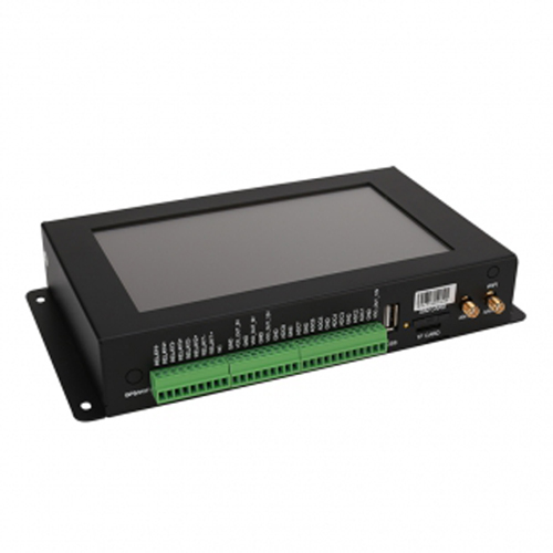
Where a complete acquisition device is preferable to custom firmware, review the NiuBoL data collector options against the required sensors and destination. The presence of several terminal blocks does not establish which ports support RS485, analog inputs or pulse counting. Obtain the specific port assignment and supply arrangement for the selected device.
Verify that the chosen port supports the required two-wire RS485 connection and Modbus RTU client operation. Some ports have selectable electrical modes; others need an optional communications module. Wire the sensor bus conductors according to the terminal definitions and provide DC power within the sensor's operating limits. Do not use an analog input as a substitute for a serial port.
Configure baud rate, data bits, parity and stop bits to match the sensor. Start with one device on a short bench connection. Poll one documented read block and inspect both the raw register words and the engineering value. In the PLC program, observe the communication function's busy, done and error states; repeatedly triggering a new request before the previous one completes can create avoidable timeouts.
The displayed register number and the protocol offset may differ. A table may label a holding register 40001 while the request uses offset 0x0000. Enter the form expected by the PLC function, not whichever number looks familiar. Also distinguish signed integers, unsigned integers and multi-register floating-point values. The sensor's data definition decides the interpretation.
Give every device on a shared segment a unique supported address. Configure duplicate factory addresses one device at a time before joining the bus. Do not allow a computer test tool and the production PLC to poll the same conventional single-client segment simultaneously; intermittent replies can otherwise be mistaken for bad sensors.
A UART TX/RX pair carries logic-level signals, not the differential RS485 bus signal. Connect the UART through a suitable transceiver. Check the supply and logic levels of the actual board and transceiver module, including the voltage returned to the MCU receive pin. Arduino is a platform name, not a universal electrical specification; the classic UNO R3 uses 5 V logic, while other boards differ.
For an ESP32 design, use a transceiver arrangement compatible with its 3.3 V logic and the exact board's pin limits. Do not assume that a module powered from 5 V has a safe receive output for a 3.3 V MCU. An isolated interface may be appropriate where grounding conditions or field wiring require it; isolation must include the intended signal and power arrangement rather than only an isolated label on one component.
Two-wire half-duplex communication requires the driver to release the bus after transmission so the sensor can reply. With manual direction control, the sequence is: enable transmit, send the complete request, wait for the final bit to leave the UART, then enable reception. Emptying a software buffer is not necessarily the same as completing physical transmission.
The ESP32 UART documentation describes half-duplex RS485 operation using an external bus driver and direction control. This facility does not by itself implement the sensor's Modbus register interpretation. Use a suitable Modbus client library and configure it for the selected UART and transceiver arrangement.
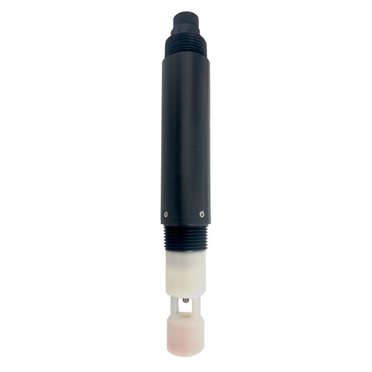
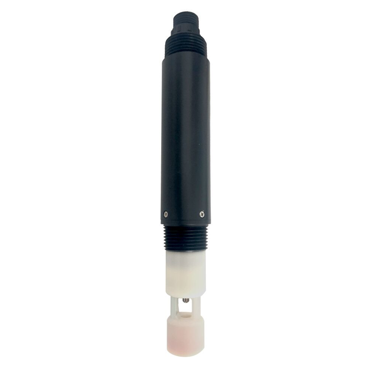
The fact that an MCU can exchange data does not mean that it can power the probe. For example, the NBL-WQ-EC-S salinity sensor requires a 12-24 VDC supply. Its RS485 data pair must not be connected to a GPIO as though it were a logic-level serial signal, and its supply must not be applied to the MCU's UART pins.
| NBL-WQ-EC-S integration item | Specification | Bench-test use |
|---|---|---|
| Power | 12-24 VDC; 0.2 W at 12 V | Use an appropriate supply and verify voltage at the sensor. |
| Output | RS485 Modbus RTU | Use an RS485-capable host interface, not a direct UART connection. |
| Default serial format | 9600 baud, 8 data bits, no parity, 1 stop bit | Check whether the delivered unit retains these settings. |
| Measurement read block | Function 0x03; start offset 0x0000; four 16-bit registers | Read the measurement and temperature values with their decimal-place fields. |
| Salinity range and resolution | 0-70.0 PSU; 0.1 PSU | Verify unit and scale rather than labeling the result conductivity. |
| Accuracy | +/-1.5% FS; temperature +/-0.5 degrees C | Keep measurement uncertainty separate from correct data decoding. |
The four-register arrangement above is a model-specific example, not a common map for every NiuBoL sensor. With a value word of 258 and a decimal-place count of 1, division by 10 gives 25.8. Use the parameter's defined unit and verify the signed interpretation of temperature separately. Do not hard-code one decimal place merely because the first sample happens to use it.
During debugging, first verify the sensor on a computer using USB-to-RS485. Record the device address, serial format, function, start offset, register count and raw reply. Then disconnect the test client and transfer those settings to the PLC or MCU. This separates a sensor or wiring problem from the host program without changing several variables at once.
Keep initial tests read-only. Do not try calibration, address changes or a factory reset simply because a read timed out. A communication fault is not evidence that measurement calibration is wrong, and a reset can remove settings needed for the application. Configure any necessary changes using the exact model procedure after basic communication is understood.
| Observed failure | Check first | Useful evidence |
|---|---|---|
| No reply from any host | Sensor supply, conductor identification, address and serial settings | Measured voltage and the exact transmitted request |
| Computer works, PLC fails | Port mode, client role, offset convention and request sequencing | PLC function status and raw register buffer |
| Computer works, MCU fails | Logic levels, TX/RX mapping and transmit-enable release timing | UART settings and a trace of request and response timing |
| Reply is valid but value is wrong | Data type, decimal scale, word order and unit | Raw words beside the calculated engineering value |
| Failures begin after adding devices | Address conflicts, bus topology, power and polling schedule | Results with devices connected individually and then together |
For field wiring, use the termination, biasing, reference-conductor and protection arrangement appropriate to the bus design and equipment. Do not install a terminating resistor at every sensor indiscriminately. Route and protect the cable for the electrical environment, and check supply voltage under operating load rather than only with the probe disconnected.
For commissioning or technical support, send NiuBoL the sensor version, host model, interface module, wiring diagram and a raw request/reply capture. Include whether the same probe works through USB-to-RS485. That information makes it possible to distinguish hardware, serial configuration and register decoding without guessing from a screenshot of the final value.
Do not assume a dedicated library is included. The required starting point is the delivered sensor's Modbus definition and wiring information. A suitable standard Modbus client library can handle transactions, while the application still needs the correct register map, scale and error handling.
Check the endpoint definitions and conductor labels with power removed before changing wiring. A/B naming conventions can differ between devices. Do not randomly swap supply and signal wires; first establish which pair is the RS485 bus.
Check whether the transceiver remains in transmit mode or switches too early and truncates the request. Also inspect UART assignment, receive logic voltage and timeout handling. A correct-looking request in a software log does not prove that the full frame reached the bus.
Not directly. Select a compatible analog-output sensor version or an active conversion device with the required scaling and fault behavior. Confirm that the chosen sensor actually offers that output; the existence of an RS485 version does not imply an analog option.
Use the startup and measurement requirements for the delivered model. Distinguish communication readiness from measurement stabilization. Mark values invalid until the necessary conditions are met instead of applying one guessed delay to every sensor type.
Only if the host configuration already supports their addresses, register maps and polling needs. Check supply capacity and cycle time as well. Each new parameter needs the correct unit, validity handling and destination tag, even when the physical bus connection is unchanged.
Connect RS485 sensors to PLCs and microcontrollers by proving the electrical path first, then the transaction and finally the engineering value. Keep a known-good bench read, use model-specific register definitions and test faults as well as normal values. For the underlying frame and register concepts, see the RS485 Modbus RTU communication guide.
Prev:Soil pH Sensor Installation and Use Guide for NBL-S-PH
Next:Multiple RS485 Sensors on One Bus: Power and Polling Limits
Related recommendations
Sensors & Weather Stations Catalog
 Agriculture Sensors and Weather Stations Catalog-NiuBoL.pdf
Weather Stations Catalog-NiuBoL.pdf
Agriculture Sensors Catalog-NiuBoL.pdf
Water Quality Sensor Catalog-NiuBoL.pdf
Related products
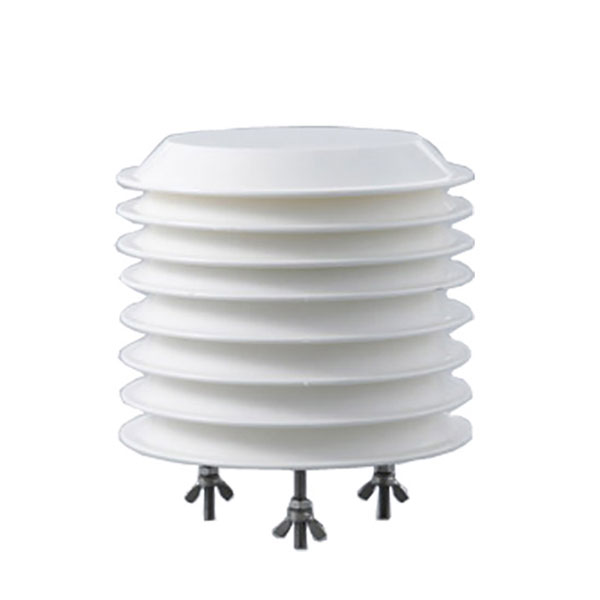 Combined air temperature and relative humidity sensor
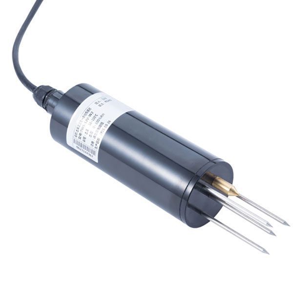 TDR Soil Moisture & Temperature Sensor for irrigation| RS485 |4-20mA| NBL-S-THR
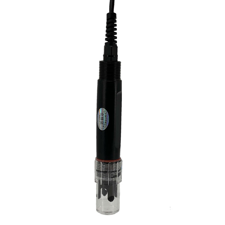 Soil pH sensor RS485 soil Testing instrument soil ph meter for agriculture |NBL-S-PH
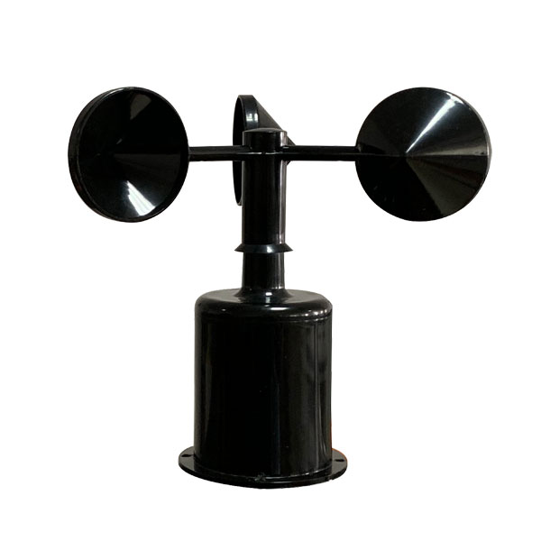 Wind Speed sensor Output Modbus/RS485/Analog/0-5V/4-20mA
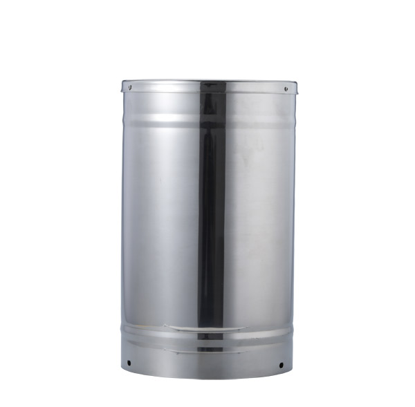 Tipping bucket rain gauge for weather monitoring auto rainfall sensor RS485/Outdoor/stainless steel
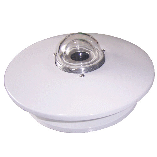 Pyranometer Solar Radiation Sensor 4-20mA/RS485

Screenshot, WhatsApp to identify the QR code
WhatsApp number:+8615367865107
(Click on WhatsApp to copy and add friends)