





— Blogs —
—Products—
 Consumer hotline +8618073152920
WhatsApp:+8615367865107
Address:Room 102, District D, Houhu Industrial Park, Yuelu District, Changsha City, Hunan Province, China
Technical Support
Time:2026-09-07 16:27:32 Popularity:331
Quick Answer: Reliable solar radiation sensor data starts with the correct measurement plane, an unobstructed view and a clean optical surface. When readings become abnormal, check raw output, wiring, scaling and timestamps before changing calibration. For a thermopile pyranometer, a small nighttime offset can occur; a persistent reading of hundreds of W/m2 in darkness calls for investigation, not an assumed solar signal.
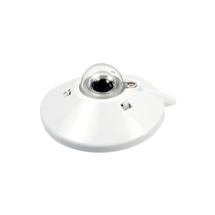
A horizontally mounted pyranometer measures global horizontal irradiance, or GHI. A sensor parallel to a photovoltaic array measures irradiance in that plane, commonly called plane-of-array irradiance. These are different measurements. Two functioning instruments can disagree because one is horizontal and the other follows a tilted array. Record the orientation with the data instead of trying to remove that difference by adjusting gain.
Choose a position with a clear view of the sky and direct sunlight through the day. Inspect the likely shadow paths of masts, antenna brackets, fences and nearby buildings. A location that is clear at noon may be shaded every morning. Repeat the exposure review when structures change or vegetation grows; a single installation photograph cannot establish year-round freedom from shading.
For horizontal measurement, adjust the leveling feet until the bubble is centered, tighten the fixings and check the bubble again. Tightening can move the instrument on an uneven mounting plate. For an intentionally tilted measurement, set the sensing plane to the required tilt and azimuth; do not level it horizontally and still label the result as array-plane irradiance.
The NiuBoL NBL-W-HPRS and NBL-W-HPRS-A installation arrangements call for the cable terminal to face north. Keep this mechanical orientation distinct from the measurement plane: it is not a reason to tilt the receiving surface toward north. Route the cable below the sensing surface, secure it against movement and leave enough strain relief that wind or maintenance work cannot pull the sensor out of alignment.
A passive thermopile, an amplified voltage output, a current transmitter and an RS485 instrument require different tests. Do not apply a generic 24 V supply to passive signal wires. Equally, a powered transmitter with its supply disconnected cannot be assessed as though it were a passive millivolt sensor.
| Parameter | NBL-W-HPRS | NBL-W-HPRS-A |
|---|---|---|
| Radiation range | 0-2000 W/m2 | 0-4000 W/m2; check the ordered output span and logger input range |
| Spectral range | 0.3-3 um | 280-3000 nm at 50% transmittance |
| Thermopile sensitivity | 7-14 uV/(W/m2) | 7-14 uV/(W/m2) |
| Response time | Up to 35 s to 99% response | Less than 5 s to 95% response |
| Nonlinearity | Up to 2% | +/-0.2% over 100-1000 W/m2 |
| Operating temperature | -40 to 50 C | -40 to 80 C |
| Output options | 4-20 mA, 0-5 V or RS485; raw thermopile output requires its calibration coefficient | Raw millivolt output; optional RS485 or 4-20 mA |
| Supply | 12 VDC or 24 VDC for the selected powered version | Passive thermopile needs no excitation; powered output versions require the specified transmitter supply |
| Calibration planning | Recalibrate sensitivity after more than two years of service | Recommended interval: two years |
Response times quoted at 95% and 99% are not directly interchangeable. Nonlinearity is one error component, not a complete accuracy statement. For measurement uncertainty, use the instrument's calibration information and include installation, cleanliness and acquisition errors. Specify cable length, jacket material, power consumption and environmental protection for the selected assembly rather than borrowing these values from another output version.
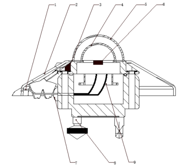
Dust, salt deposits, pollen and dried water marks alter the light reaching the thermopile. Inspect the outer dome and bubble level together. Establish the inspection frequency from the actual fouling rate: a dusty construction site or coastal location may need attention much sooner than a clean, accessible reference site. A fixed monthly interval is not a reliable rule for every installation.
The dome and leveling arrangement are part of the measurement system, not cosmetic fittings. Internal condensation in an NBL-W-HPRS-A calls for return-for-service assessment. On instruments with a serviceable desiccant arrangement, use the correct service procedure for that design; do not assume every sealed pyranometer has a user-replaceable dryer.
For a passive thermopile, irradiance equals output voltage divided by the individual sensitivity. Keep the units consistent. If the calibration coefficient is 10 uV/(W/m2), an output of 8 mV is 8000 uV, corresponding to 800 W/m2. This is a worked example, not a coefficient to enter into every instrument.
Record the serial number and its coefficient together. Replacing a probe without updating that coefficient can produce plausible-looking but systematically wrong readings. Choose a logger input that resolves millivolts adequately and accepts the expected small negative offset. A general-purpose 0-10 V input may not provide sufficient usable resolution for a raw thermopile.
For an NBL-W-HPRS ordered with 4-20 mA corresponding to 0-2000 W/m2, calculate irradiance as (current in mA - 4) / 16 x 2000. Thus, 12 mA corresponds to 1000 W/m2. A 0-5 V version over the same span gives 1000 W/m2 at 2.5 V. Use these relationships only for those specified spans; do not apply them automatically to the HPRS-A or a customized transmitter.
Verify the receiving channel independently with a suitable signal source, after disconnecting and isolating the sensor according to the electrical procedure. Inject into the logger input, not into the thermopile. If the simulated value is already wrong on the display, investigate the acquisition configuration before sending the sensor for calibration.
For the HPRS-A digital option, the serial settings are 9600 bps, eight data bits, no parity and one stop bit, with function 03 used for reading. Match the configured device address and the applicable register definition. The base HPRS has its own interface details; do not copy an HPRS-A wiring color or driver into it without checking the output version.
Compare the returned register value with the local logger and remote platform at the same timestamp. An online device indicator only establishes that some communication is occurring. It does not prove that the displayed radiation value is newly sampled or correctly scaled. Diagnose address collisions, stale values and unit conversion separately.
| Observed pattern | First checks | What the result helps distinguish |
|---|---|---|
| A dip at approximately the same solar position on clear days | Inspect the shadow path across the dome | Local obstruction versus a general sensitivity change |
| Consistently high or low by a similar factor | Check sensitivity, input span, gain and unit conversions | Scaling error versus optical contamination or sensor drift |
| Hundreds of W/m2 during darkness | Read raw output, timestamp and channel mapping; inspect current-loop offset handling | Stale or misinterpreted data versus a genuine signal problem |
| Intermittent spikes in windy conditions | Inspect cable movement, connector seating, shield arrangement and power interruptions | Electrical intermittency versus rapid cloud-driven changes |
| A flat maximum during bright conditions | Check sensor output span, logger range and software limits | Clipping in one stage of acquisition |
| No response to a change in illumination | Check the correct output type, powered-version supply, raw signal and update time | Sensor fault versus disconnected acquisition or frozen display |
Do not force all nighttime samples to zero before investigating an offset. Thermopile thermal exchange can produce small negative values, and filtering them away can hide a developing change. Preserve the unmodified values for diagnosis; apply any operational data-quality rule in a separate processing step with its meaning documented.
A side-by-side comparison can reveal a large discrepancy when both instruments have the same plane, clear exposure, clean domes and aligned timestamps. Compare stable periods across several irradiance levels and consider each instrument's response time. A fast reference and a slower sensor can differ during moving clouds without either having a steady-state gain fault.
Do not derive a new calibration coefficient from one sunny reading or from a nearby weather website. Recalibration requires an appropriate reference and a controlled comparison procedure. For HPRS-A service planning, use the recommended two-year interval as a starting point, with earlier assessment after damage, internal moisture or persistent unexplained disagreement. Project-specific quality requirements may call for a different schedule.
When requesting support from NiuBoL, send the model, serial number, output version, coefficient where applicable, mounting photographs, cleaning history and a short synchronized series of raw and displayed values. Include the logger configuration and when the problem first appeared. This makes it possible to distinguish a sensor service requirement from an input-range or installation correction.
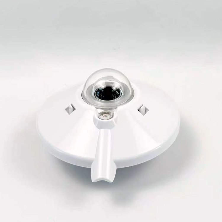
No. Horizontal mounting is used for GHI, while a tilted sensor measures radiation incident on its own plane. Match the plane to the required quantity and store the orientation with the record. Leveling a sensor intended to follow a tilted array changes what it measures.
No. Rain may leave mineral marks or redistribute dirt, and dried deposits can remain on the glass. Inspect the dome after relevant weather or site events and clean according to its condition. Do not use rainfall as evidence that the optical surface is clean.
No. The obstruction changes with solar position and the mix of direct and diffuse radiation. Move the obstruction or sensor where practical, and flag affected periods. A constant multiplier cannot reconstruct the missing irradiance reliably.
No. Raw thermopile sensitivity is individual to the instrument. Use the replacement's coefficient and verify the logger calculation. For an amplified or digital output, establish whether conversion occurs inside the sensor so that sensitivity is not applied a second time.
Not necessarily. Thermopile zero offset can produce small negative values. Assess the size and trend, installation conditions and input configuration. A sudden or large change needs investigation; deleting all negative values is not a diagnostic test.
No. First establish that the raw signal, power where required, wiring and acquisition scaling are correct. Calibration cannot repair a loose connector, an incorrect current span or a stale platform value. Request recalibration when the measurement chain is functioning but an unexplained sensitivity discrepancy remains.
Solar radiation sensor maintenance combines optical inspection, alignment checks and electrical diagnosis. Keep the dome clean, distinguish horizontal from array-plane irradiance, and trace an abnormal reading back to its raw signal. Correct installation and acquisition errors first; use calibration to address sensitivity, not to compensate for shade, dirt or incorrect units.
Prev:Ultrasonic Wind Sensor Installation: North Alignment and Moving Platforms
Next:Water Quality Sensor Installation: Immersion, Buoy, Flow Cell and Pipeline
Related recommendations
Sensors & Weather Stations Catalog
 Agriculture Sensors and Weather Stations Catalog-NiuBoL.pdf
Weather Stations Catalog-NiuBoL.pdf
Agriculture Sensors Catalog-NiuBoL.pdf
Water Quality Sensor Catalog-NiuBoL.pdf
Related products
 Combined air temperature and relative humidity sensor
 TDR Soil Moisture & Temperature Sensor for irrigation| RS485 |4-20mA| NBL-S-THR
 Soil pH sensor RS485 soil Testing instrument soil ph meter for agriculture |NBL-S-PH
 Wind Speed sensor Output Modbus/RS485/Analog/0-5V/4-20mA
 Tipping bucket rain gauge for weather monitoring auto rainfall sensor RS485/Outdoor/stainless steel
 Pyranometer Solar Radiation Sensor 4-20mA/RS485


Screenshot, WhatsApp to identify the QR code
WhatsApp number:+8615367865107
(Click on WhatsApp to copy and add friends)

