





— Blogs —
—Products—
 Consumer hotline +8618073152920
WhatsApp:+8615367865107
Address:Room 102, District D, Houhu Industrial Park, Yuelu District, Changsha City, Hunan Province, China
Technical Support
Time:2026-09-07 16:27:31 Popularity:350
Ultrasonic wind sensor installation requires two separate checks: the instrument must see the intended airflow, and its direction reference must be correct. On a fixed mast, level the sensor and align its reference mark to the specified north reference, normally true north for meteorological records. On a moving platform, alignment alone is insufficient: earth-referenced wind also requires platform orientation and velocity. Confirm the output at the logger, not only on the sensor display.
Before lifting the sensor onto a mast, write down the direction convention used by the project. Meteorological wind direction normally describes where the wind comes from: a northerly wind arrives from north. A controller or vector-processing routine may instead use the direction toward which the air moves. Confusing these conventions produces a 180-degree error even when the sensor is correctly aligned.
Also distinguish true north, magnetic north and the instrument's local reference. A sensor mounted facing the front of a vehicle can report platform-relative direction correctly while still giving the wrong earth-referenced direction. Label that channel as relative wind until the required transformation has been applied.
Do not rely on a displayed direction alone to identify the convention. Check the configured reference, the physical mark and a controlled direction test. Preserve the original sensor output during commissioning so a correction applied in the logger can be distinguished from one applied inside the sensor.
Buildings, trees, roof edges, solar panels and mast members can redirect or shelter the airflow. A rigid bracket does not solve that exposure problem. For representative weather monitoring, choose an open position appropriate to the project's siting requirements. For a local airflow study, record the obstacle geometry because the disturbed flow may be the quantity of interest.
Inspect the proposed position from several wind directions. A sensor that is clear of the pole in one sector may lie behind it in another. Put the acoustic measurement paths clear of brackets and cable loops, and avoid mounting directly in a fan outlet unless the fan flow is intentionally being measured.
There is no single mast height that makes every installation representative. A roof-mounted sensor and a free-standing mast can observe different flows at the same nominal height above ground. Record the sensor height, nearby obstruction heights and their directions so later comparisons are made on an informed basis.
A compass-equipped version still needs an installation check. Steel poles, protective boxes and nearby current-carrying conductors can affect magnetic heading. A software heading output should not be treated as proof of true-north alignment without checking its reference and the installed environment.
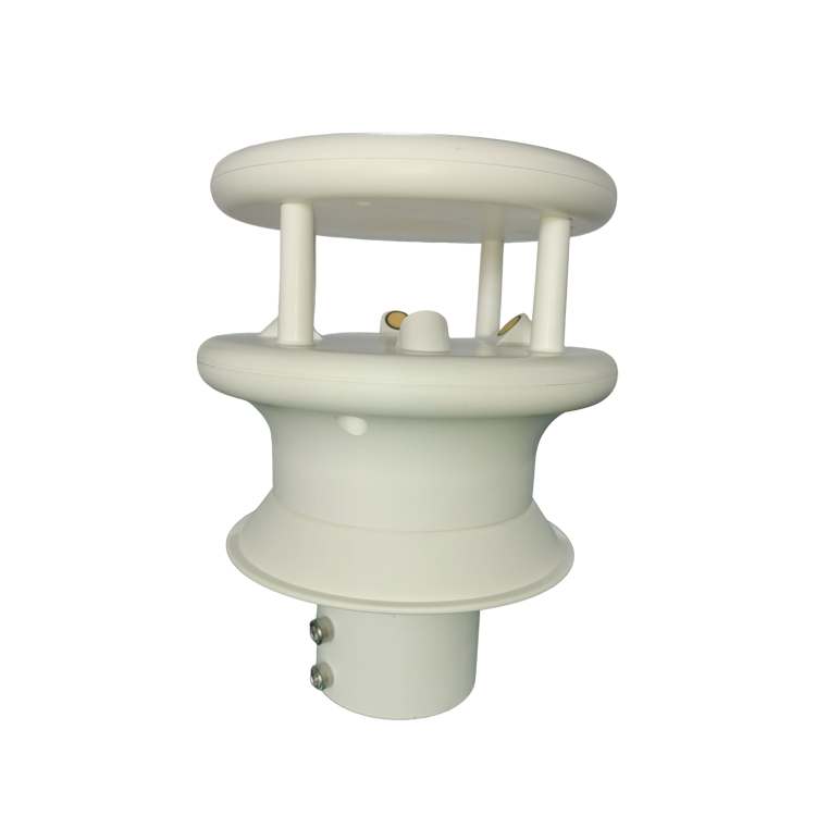
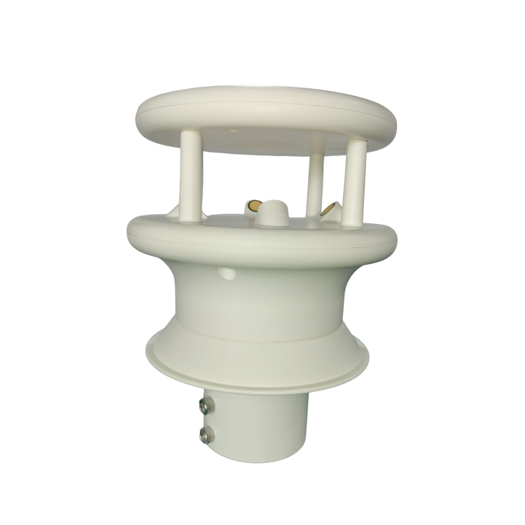
The NiuBoL NBL-W-21GUWS ultrasonic wind speed and direction sensor supplies horizontal wind measurements over RS485 Modbus RTU. Bench-test the selected sensor with its intended data logger before mast installation; this separates addressing and scaling faults from problems caused by the final cable run.
| Installation item | NBL-W-21GUWS value | Check at commissioning |
|---|---|---|
| Supply voltage | 12-24 VDC | Measure at the sensor end with the equipment operating |
| Communication | RS485 Modbus RTU; 9600 baud | Match address and serial settings to the logger configuration |
| Wind speed | 0-60 m/s; 0.01 m/s resolution | Apply the correct register scale; resolution is not accuracy |
| Wind direction | 0-359 degrees; 1-degree resolution | Check north reference and the wrap from 359 to 0 degrees |
| Operating environment | -20 to 80 C; IP65 | Check the actual exposure and keep connectors correctly sealed |
| Optional heating | 3 W heater | Allow for the heater separately from sensing, logging and communications loads |
Wire by the terminal identification and the supplied cable label. Do not assume that cable colors from another wind sensor have the same function. Keep power conductors and the RS485 pair correctly identified through intermediate junctions. A reversed data pair may stop communication; a power-to-data wiring error can damage the interface.
Use a bus arrangement appropriate to RS485 and install termination and biasing to suit the actual network. Each sensor needs a unique address. Check protective-earth and surge arrangements with the station designer; a cable shield is not a substitute for lightning protection or a properly designed grounding system.
In the NBL-W-21GUWS register format, wind speed uses a 0.01 m/s scale and direction uses whole degrees. A raw speed value of 272 therefore represents 2.72 m/s, while a direction value of 176 represents 176 degrees. Verify those values in a raw response and in the logger display before enabling remote reporting. Leave at least 1,000 ms between communication requests for this configuration; faster polling should not be assumed to improve the measurement rate.
A three-dimensional ultrasonic anemometer measures components along its own axes. Identify which physical direction is positive X, positive Y and positive Z, then record how those axes relate to the site's coordinates. Do not substitute a generic east-north-up convention unless it matches the actual device output or a documented transformation.
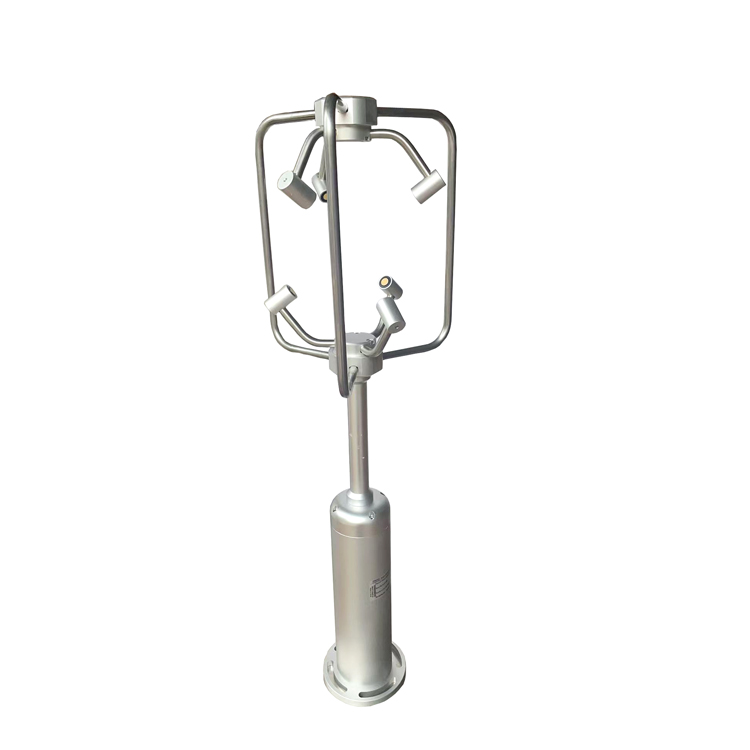
Tilting the instrument mixes components: horizontal flow can appear in the reported vertical channel. Leveling is therefore not merely a cosmetic installation step. Where a research method applies coordinate rotation after acquisition, retain the raw components and mounting orientation so the processing can be repeated.
Check negative component values explicitly at the receiving system. The correct interpretation depends on the register encoding of the installed version. A plausible positive speed does not prove that signed X/Y/Z channels are being decoded correctly.
A sensor on a vehicle or vessel measures airflow relative to its moving mounting point. Rotating that reading using heading puts the vector into another coordinate frame, but the effect of the platform's motion remains. True-wind calculation requires compatible motion and orientation measurements, with consistent timestamps.
NOAA's shipboard wind data description illustrates this distinction: earth-referenced wind is calculated from relative wind together with GPS motion and heading. Heading and course over ground are not interchangeable; a vessel can point in one direction while drifting along another.
Consider a simple example: a platform travels east at 5 m/s through still air. It senses an apparent wind from the east at approximately 5 m/s. Correcting only for its heading still leaves that apparent wind. Combining the air-velocity vector with the platform's eastward velocity gives zero earth-referenced wind in this idealized case.
In practical processing, first express the measured air velocity and platform velocity in the same coordinates, then combine them with the correct sign convention. Convert the resulting vector into meteorological speed and direction afterward. Do not add scalar wind speeds or subtract compass bearings.
Pitch, roll and rotational movement can add further errors, especially when the sensor is mounted far from the platform's motion reference point. A mobile research system may need attitude and angular-motion compensation as well as translation. Confirm those functions at system level; neither a compass nor a third wind axis supplies all of them automatically.
Run a direction check at a known sensor orientation, then rotate or reorient the test arrangement in a controlled manner. Verify the expected direction change, the north wrap and the absence of a duplicated offset. Use suitable controlled airflow for a functional check; blowing across the sensor by mouth is not a wind-speed calibration.
Compare sensor responses with the raw logger record and the remote display. Check units, timestamps and stale-data behavior. When communication is interrupted, the system should identify missing data rather than continue presenting the last value as a fresh observation.
For a side-by-side reference test, use comparable exposure and averaging intervals. Two instruments on opposite sides of a mast can disagree because of wake effects. Investigate a direction-dependent difference before adjusting calibration. On a mobile platform, add stationary and moving trials to distinguish alignment errors from incomplete motion compensation.
Finish with an inspection of cable strain relief, drip loops, connector seals and service access. IP65 does not establish resistance to every salt-spray or icing environment. At exposed coastal sites, select suitable materials and an inspection routine; keep the transducer paths clear without scraping or chemically treating surfaces by an unapproved method.
Use the reference specified for the project. For a true-north meteorological record, a magnetic compass reading needs the appropriate declination treatment. Confirm whether any correction occurs in the sensor or logger so it is applied only once.
A known fixed horizontal offset can be corrected if the system supports it and the convention is documented. Software cannot remove airflow distortion from a building or correct an unknown change in mounting orientation.
Check whether one system reports where wind comes from and another where it travels toward. Also inspect the physical reference mark and any configured offset. Correct the convention before applying an arbitrary additional 180-degree adjustment.
The wind sensor may be suitable for both configurations, but the processing requirements differ. A vessel needs motion and orientation data for earth-referenced wind, plus installation checks for magnetic interference and platform-induced flow distortion.
Check sensor tilt, axis decoding and nearby obstructions before concluding that the vertical channel is faulty. Local vertical airflow may also be real. Compare with a suitable reference and preserve the component data rather than forcing the vertical output to zero.
Send the sensor model, mounting photographs, direction reference, supply measurement and logger settings. For a moving platform, include the required relative or earth-referenced output and the available heading, position and motion channels.
A successful ultrasonic wind sensor installation keeps airflow exposure, orientation and data interpretation consistent. On a fixed mast, verify level, north reference and the final logger values. On a moving platform, add the required motion transformation before labeling the result as true wind. These checks prevent a functioning sensor from producing a misleading weather record.
Prev:How to Install Soil Sensors for Representative Field Data
Next:Solar Radiation Sensor Installation, Cleaning, Calibration and Abnormal Data Checks
Related recommendations
Sensors & Weather Stations Catalog
 Agriculture Sensors and Weather Stations Catalog-NiuBoL.pdf
Weather Stations Catalog-NiuBoL.pdf
Agriculture Sensors Catalog-NiuBoL.pdf
Water Quality Sensor Catalog-NiuBoL.pdf
Related products
 Combined air temperature and relative humidity sensor
 TDR Soil Moisture & Temperature Sensor for irrigation| RS485 |4-20mA| NBL-S-THR
 Soil pH sensor RS485 soil Testing instrument soil ph meter for agriculture |NBL-S-PH
 Wind Speed sensor Output Modbus/RS485/Analog/0-5V/4-20mA
 Tipping bucket rain gauge for weather monitoring auto rainfall sensor RS485/Outdoor/stainless steel
 Pyranometer Solar Radiation Sensor 4-20mA/RS485


Screenshot, WhatsApp to identify the QR code
WhatsApp number:+8615367865107
(Click on WhatsApp to copy and add friends)

