

— Blogs —
—Products—
 Consumer hotline +8618073152920
WhatsApp:+8615367865107
Address:Room 102, District D, Houhu Industrial Park, Yuelu District, Changsha City, Hunan Province, China
Product knowledge
Time:2026-09-19 09:00:00 Popularity:203
Conductivity sensor selection for industrial water starts with the operating span at each measuring point. An RO feed line, permeate outlet and concentrated process stream may need different electrode configurations even when their signals go to the same PLC. Choose range and allowable error together, then check temperature compensation, wetted materials and installation geometry. A wide range is useful only if it still resolves the change that matters at the normal operating level.
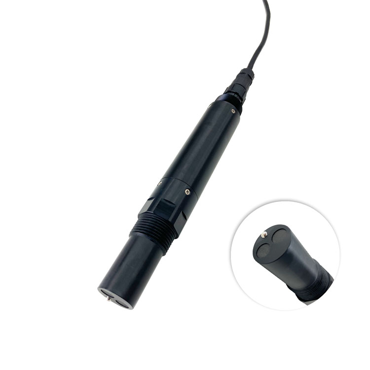
An industrial-water project often has several conductivity duties. Feed monitoring follows changes entering treatment. Permeate monitoring looks for small changes after ion removal. A rinse-water point may control when a batch can move to the next step, while a concentrated return stream needs to remain measurable during process excursions. Using one probe specification everywhere simplifies a parts list but can weaken the most demanding measurement.
Provide expected minimum, normal and maximum values in the RFQ, especially when the project covers both treated water and raw water. This information should come from site measurements or a process design basis. Include startup flushing and cleaning exposure separately: the highest liquid conductivity during maintenance may not be the range needed for a valid production reading.
| Measuring point | Selection priority | Common specification error |
|---|---|---|
| RO feed | Cover normal source variation and credible excursions | Choosing from one low-season sample |
| RO permeate | Demonstrate adequate uncertainty around the product-water decision | Reusing a feed-range probe because its maximum includes zero |
| Process rinse | Distinguish the rinse endpoint in the actual chemical matrix | Treating any conductivity reduction as proof of complete chemical removal |
| Concentrated process return | Match high conductivity, chemical exposure and electrode geometry | Buying a low-range cell and relying on software rescaling |
A conductivity signal is not selective for a particular contaminant. It may indicate ionic carryover without identifying the ion, and a low result does not rule out nonionic contamination. Where a release decision concerns a specific chemical, retain the measurement required for that chemical instead of extending the conductivity alarm beyond its purpose.
The NiuBoL NBL-WQ-EC has several range configurations. They are selection options, not proof that every delivered probe can switch between them while keeping the same electrode and accuracy. Specify the ordered range and sensor configuration together.
| NBL-WQ-EC range option | Resolution | Error term at the specified +/-1% full scale |
|---|---|---|
| 0-20.00 uS/cm | 0.01 uS/cm | +/-0.20 uS/cm |
| 0-200.0 uS/cm | 0.1 uS/cm | +/-2.0 uS/cm |
| 0-5000 uS/cm | 1 uS/cm | +/-50 uS/cm |
| 0-200.0 mS/cm | 0.1 mS/cm | +/-2.0 mS/cm |
The final column converts the NBL-WQ-EC specified +/-1% full-scale accuracy into absolute units for each range. It is not the complete uncertainty of an installed system. A 0-5000 uS/cm configuration has a +/-50 uS/cm term, which does not establish the ability to distinguish 5 uS/cm from 10 uS/cm. A display increment of 1 uS/cm does not fix that problem. Keep the separate EC-4A accuracy specification with that model; do not transfer its percentage to the EC range table.
Conversely, selecting 0-20 uS/cm solely for better resolution can cause overrange during a real event. If the site needs both fine low-level discrimination and measurement of much larger excursions, ask for an architecture that meets both requirements. Options may include separately ranged points or a different validated instrument; silently clipping the upper values is not an acceptable substitute.
Conductivity changes with temperature. A feed value corrected to a reference temperature cannot be compared directly with an uncompensated permeate value taken at another temperature. Record which output is being used and where compensation occurs. A Pt1000 temperature element provides the temperature input; it does not make one correction coefficient valid for every water composition.
For RO trending, an apparent conductivity rejection can be calculated as 100 x (1 - permeate conductivity / feed conductivity), provided the readings are representative and on a comparable basis. For an illustrative feed of 1000 uS/cm and permeate of 20 uS/cm, the result is 98%. This is a conductivity-based operating indicator, not proof of rejection for every dissolved constituent.
That percentage also inherits the uncertainty of both instruments. A permeate reading of 20 uS/cm from a device with a +/-50 uS/cm full-scale term cannot support a precise rejection claim. Choose the downstream range for the downstream decision. Compare process pressure, flow and operating state before interpreting a change in the calculated percentage as a membrane defect.
For low-conductivity water, keep the sampling path closed and clean where the design permits. Exposure to air, residue in a reused cup and contamination from an unsuitable fitting can change the water being measured. Taking a sample into an open vessel is not automatically an equivalent comparison with the installed flow-through point.
| Installation item | NBL-WQ-EC | NBL-WQ-EC-4A |
|---|---|---|
| Range basis | Ordered range from the options above | 0-5000 uS/cm; 1 uS/cm resolution |
| Power supply | 12-24 V DC +/-10% | 12-24 V DC |
| Power consumption | 0.2 W at 12 V | 0.2 W at 12 V |
| Signal | RS485 Modbus RTU | RS485 Modbus RTU; optional 4-20 mA |
| Water conditions for design review | 0-50 C; pressure below 0.6 MPa | Liquid 0-50 C; pressure below 0.6 MPa |
| Mounting and protection | 3/4 NPT; immersion installation; IP68 | 3/4 NPT; immersion installation; IP68 |
| Wetted material options | ABS, SUS316L or PVC configuration | ABS / SUS316L configuration |
| Cable | Standard 5 m; four-core shielded connection | Standard 5 m; five-core shielded cable for the optional current channel |
Use 0-50 C as the liquid-temperature envelope when screening these applications. Hot cleaning, steam exposure and high-pressure wash cycles need a separate suitability assessment; IP68 is not a chemical-resistance or steam-sterilization rating. Check every wetted part, including the holder and seals, against the complete exposure rather than only the production water.
For the EC-1.0 and EC-4A configurations, provide at least 2 cm clearance from the sensing region to container walls and the bottom during installation and testing. A tight tee may violate this geometry even when its thread matches. Keep the active region immersed and free of trapped air. Never remove a probe from a pressurized fitting without the site's isolation procedure.
If an existing PLC requires a current input, order the EC-4A's 4-20 mA option explicitly. Check loop wiring and scaling with the receiving card. The RS485-only EC probe cannot supply current merely because the cable has spare conductors. For Modbus, confirm the exact register format and unit; confusing mS/cm with uS/cm creates a factor-of-1000 error.
Test near the normal operating level and near the intended decision threshold, using appropriate standards or a suitable reference procedure. A successful check at high conductivity alone says little about a low-range permeate duty. Allow the sensor and reference to reach comparable temperature and avoid carrying concentrated standard into a low-conductivity test.
Inspect the effect of mounting as well as calibration. Compare the probe in a suitable test vessel and its final holder under equivalent conditions. A discrepancy that appears only after installation warrants checking clearance, bubbles and sample contamination before adjusting coefficients. Record the configuration and selected range so a later spare is not ordered merely by the family name.
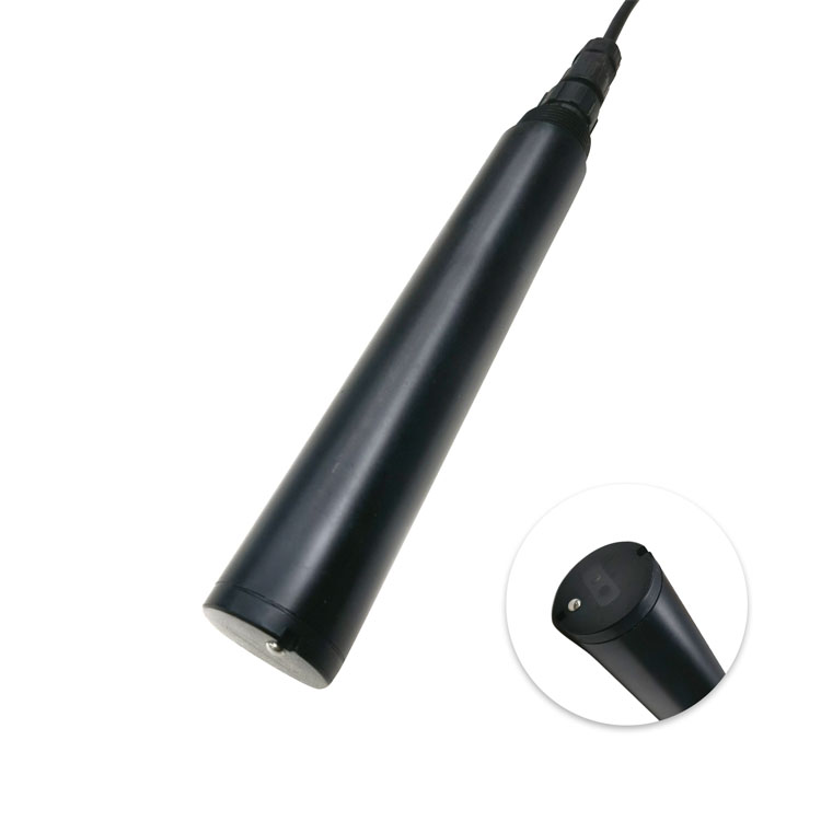
Conductivity sensor selection may also expose a separate particle-monitoring need. Conductivity cannot indicate filter breakthrough caused only by nonconductive particles. A turbidity channel in a multi-parameter arrangement, illustrated below, answers a different question; its presence does not improve the EC channel's low-range accuracy.
Only when its range, uncertainty and physical installation satisfy both duties. In many projects the two points need different range configurations. Establish the required discrimination at the permeate outlet first, then compare it with the guaranteed error rather than simply checking that both readings fall below the maximum range.
No. The low-range option must still meet the required uncertainty, sample-handling and reporting conditions. For very low conductivity, contamination and temperature effects can dominate. A range starting at zero is not evidence of validated ultrapure-water performance or compliance with a particular production standard.
Not if the full-scale error makes today's decision unreliable. Future expansion can be handled with another correctly ranged channel. Request a documented multi-range capability only where it is actually available; do not assume software can turn an unsuitable electrode configuration into a different sensor.
List each measuring point with its normal and maximum conductivity, required alarm discrimination, liquid temperature, pressure, chemicals and mounting drawing. State whether the host needs RS485 or 4-20 mA. Ask for the selected range, wetted materials, cable and verification procedure to be identified in the offer.
It can support an endpoint where the relevant ionic carryover has a validated relationship with conductivity. It cannot rule out all nonionic residue or identify every chemical. Establish that relationship with the process owner and retain any chemical-specific or hygiene testing the release decision requires.
Its optional 4-20 mA output can support an analog input when the range and installation also fit. Confirm that the option is supplied, define the scale at both ends and test the complete loop. Selecting it solely for the current output is insufficient if the water requires a different conductivity range.
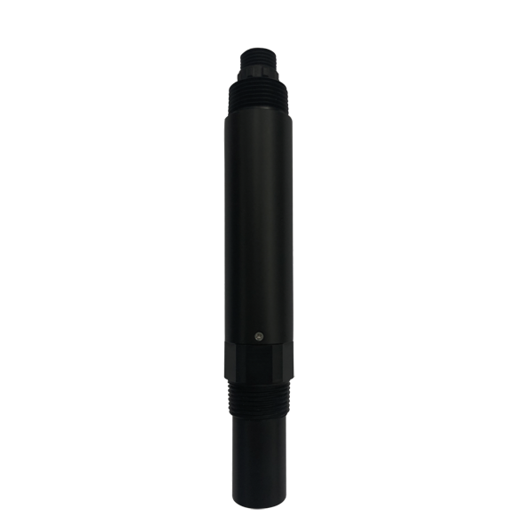
Conductivity sensor selection for industrial water should produce a point-by-point range schedule, not one universal probe specification. Select NiuBoL EC configurations around the required discrimination, keep feed and permeate data on a consistent temperature basis, and verify the final holder and host input. These details make quotations comparable and prevent a convenient interface from hiding a poor measurement match.
Prev:DO Monitoring in Parallel Aeration Tanks: Shared-Air Header Decisions
Next:TDS, Conductivity and Salinity: Which Parameter Should a Water Project Specify?
Related recommendations
Sensors & Weather Stations Catalog
 Agriculture Sensors and Weather Stations Catalog-NiuBoL.pdf
Weather Stations Catalog-NiuBoL.pdf
Agriculture Sensors Catalog-NiuBoL.pdf
Water Quality Sensor Catalog-NiuBoL.pdf
Related products
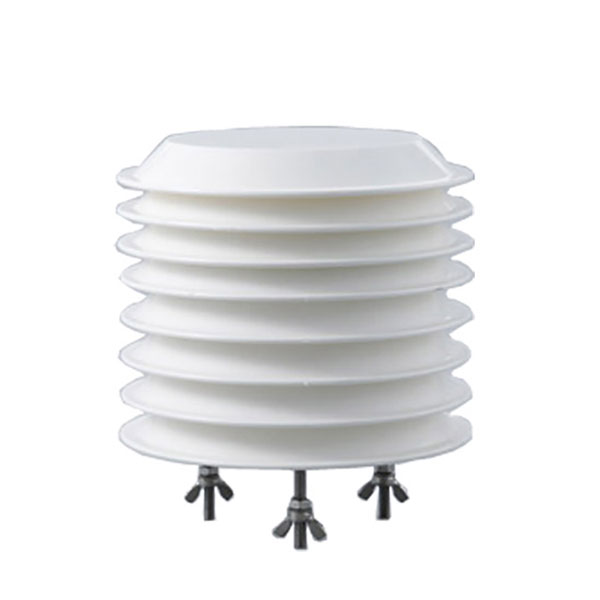 Combined air temperature and relative humidity sensor
 TDR Soil Moisture & Temperature Sensor for irrigation| RS485 |4-20mA| NBL-S-THR
 Soil pH sensor RS485 soil Testing instrument soil ph meter for agriculture |NBL-S-PH
 Wind Speed sensor Output Modbus/RS485/Analog/0-5V/4-20mA
 Tipping bucket rain gauge for weather monitoring auto rainfall sensor RS485/Outdoor/stainless steel
 Pyranometer Solar Radiation Sensor 4-20mA/RS485

Screenshot, WhatsApp to identify the QR code
WhatsApp number:+8615367865107
(Click on WhatsApp to copy and add friends)