

— Blogs —
—Products—
 Consumer hotline +8618073152920
WhatsApp:+8615367865107
Address:Room 102, District D, Houhu Industrial Park, Yuelu District, Changsha City, Hunan Province, China
Product knowledge
Time:2021-11-28 22:31:39 Popularity:2517
Quick Answer: RS485 vs RS232 is primarily a choice of electrical interface and connection topology. RS232 suits a compatible point-to-point serial link; RS485 supports differential signalling and shared field buses. Neither defines the sensor's data meaning. Confirm the application protocol, pinout, power and serial settings separately before connecting a sensor to a PLC, RTU or data logger.
| Item | RS232 | RS485 |
|---|---|---|
| Signaling | Single-ended relative to signal ground | Differential pair, with common-mode limits defined by the transceivers |
| Typical topology | Point to point | Linear bus; two-wire half duplex is common, while four-wire arrangements also exist |
| Multiple devices | Not designed as a multidrop field bus | Possible when transceiver loading, addressing and protocol rules permit it |
| Noise environment | More sensitive to ground offset and coupled noise over long runs | Differential reception provides better rejection of common interference |
Do not connect either interface directly to a bare TTL UART unless a suitable transceiver or converter is included. Similar names such as TX and RX can appear on electrically different ports. The supply voltage of a sensor is also separate from the signal levels on its communication terminals.
An RS485 sensor may contain four conductors: power positive, power return and the differential pair. Calling it a two-wire RS485 link describes the signal pair, not necessarily the complete cable. Check whether a signal reference conductor is required and how it relates to the power return and shield in that installation.
There is no responsible single maximum distance for every RS485 installation. Cable characteristics, data rate, driver strength, receiver design, topology, termination and electrical noise all matter. Longer runs generally require a lower data rate and better installation discipline. Use the equipment manuals and a link calculation, then test the final network.
Likewise, a connector shape does not identify the interface. RS232 often uses a D-sub connector, but RS485 may use screw terminals, circular connectors or another manufacturer-defined pinout. Never wire by connector appearance.
Treat familiar figures such as roughly 1200 m or 10 Mbit/s as design-context references, not a promise that both can be achieved together. Edge speed, cable attenuation and reflections affect the receiver even when the configured baud rate looks modest. A slow application does not automatically make any wiring layout acceptable.
For a long agricultural cable route, also calculate the voltage at the sensor. For an illustrative two-conductor power loop with 20 ohms resistance carrying 0.1 A, the drop is 2 V. A sensor might communicate correctly on a short bench lead yet reset in the field when its supply falls below its operating limit. Improving the data pair alone would not fix that power problem.
Identify the actual two ends of the cable trunk. The controller is not necessarily at one end if the cable continues in both directions. Do not add an end-of-line resistor at every transmitter: multiple parallel terminations increase the load on the driver and can reduce the signal.
With power removed and other circuit effects accounted for, two 120 ohm end resistors in parallel give approximately 60 ohms across the pair. Three give approximately 40 ohms. This is a useful diagnostic clue, not a complete acceptance test; connected electronics and bias networks can affect the meter reading. Never use resistance mode on an energized bus.
Shield, signal reference and protective earth perform different functions. Differential reception tolerates only a finite common-mode voltage, so isolation and grounding require a deliberate site design. A cable shield is not an arbitrary substitute for the reference arrangement, and connecting grounds without evaluating site potential differences can create a new problem.
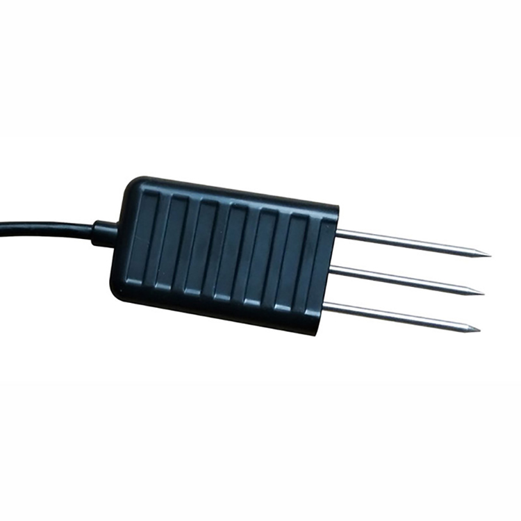
A/B labelling is not sufficiently consistent across all equipment to justify wiring by letter alone. Match the terminal definitions supplied for both devices. For example, the NiuBoL NBL-S-TMC connection uses yellow for A+/TX and blue for B-/RX, with red supply positive and black return. Those colours must not be generalized to every NiuBoL sensor or another instrument.
On a two-wire half-duplex bus, a transmitter must release the pair before the next device replies. A converter with unsuitable direction timing can lose the start of a response even though the baud rate is correct. Confirm that an RS232-to-RS485 converter supports the intended two-wire operation and response timing; a passive connector adaptor cannot perform that electrical conversion.
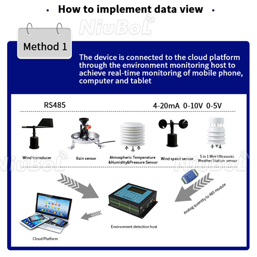
RS485 carries bits; it does not provide register addresses. Modbus RTU adds device addressing, function codes and data framing. Before connecting a sensor to a PLC or logger, confirm baud rate, parity, stop bits, address, register map, scaling and byte order.
A transparent serial converter normally changes the electrical transport, not the message meaning. A sensor speaking a proprietary ASCII command set will not become Modbus RTU merely by passing through an RS485 converter. A protocol gateway needs explicit support for both the source and destination data models.
Likewise, two Modbus devices may expose different registers, units and scale factors. A soil value of 237 might mean 23.7% VWC in one defined mapping, while another instrument uses a different representation. Verify a plausible value against a known condition and the register definition instead of assuming that any changing number is correctly decoded.
The classic RS485 electrical loading reference is 32 unit loads. A device can represent a fraction of a unit load, but biasing and the complete transceiver network also matter. Modbus serial addresses 1-247 are a protocol allocation, not proof that 247 attached devices will meet the electrical and response-time requirements of one cable segment.
Budget the polling cycle as well. As an illustrative minimum wire-time calculation, an 8-byte request and 9-byte reply contain 17 characters. With 11 bits per character at 9600 bit/s, transmitting those characters takes about 19.5 ms. Device processing, frame separation and turn-around add time. A one-second timeout on a missing device can dominate a cycle that otherwise has short replies.
Limit retries and define stale-data handling so one absent sensor does not prevent timely collection from the remaining network. A last valid value can be retained for investigation, but its age must remain visible to the controller or operator. A static display without a timestamp is not proof of a healthy link.
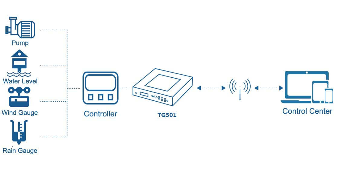
NiuBoL's RTU acquisition equipment includes configurations with RS232 and RS485 ports. A dedicated RS232 debug port is not necessarily an additional freely programmable field channel. Check the selected device's port allocation and operating modes before assigning sensors.
A data logger, PLC or gateway must perform the required serial master function if the sensors expect polling. Remote transport, local storage and Modbus TCP conversion are separate functions to confirm. A product having both interfaces does not mean that all ports automatically bridge or that several masters can share one serial bus.
Begin with one device on a short known-good connection. Verify its power, pinout, serial format and an explicit read transaction. Add devices or cable sections incrementally, assigning unique addresses before connecting identical factory-default units together. Keep an unchanged working baseline for comparison.
If no reply is received, separate power, electrical and protocol checks. Verify voltage under load, the selected physical port, A/B or TX/RX definitions, and whether the converter is transmitting. Then review address, function, register and response timing. Reversing random wires repeatedly obscures which change produced a result.
If faults appear only when a pump or inverter operates, inspect cable routing, supply disturbances and reference potentials before changing register settings. If replies arrive with valid framing but impossible values, investigate scaling, signed interpretation and register order. A repeatable decoding error is not normally cured by adding another termination resistor.
For a remote field system, repeat the checks with the final cable route, enclosure, power source and normal equipment operating. Bench success establishes a useful starting point; it does not validate a kilometre-scale installation or a cabinet with active drives.
No. Use a suitable active converter and confirm protocol compatibility, serial format and direction control. A pin adaptor alone cannot translate single-ended and differential signalling.
No. RS485 describes the electrical interface. The connected devices must also share an application protocol and compatible message definitions. Confirm the exact protocol rather than ordering from the interface name alone.
Evaluate electrical unit loading, biasing, cable layout, power distribution and polling time. The available Modbus address range and a historical RS485 node count are different constraints; neither alone determines a workable system size.
No. Distance depends on the transceivers, rate, cable, topology and electrical environment. Validate the selected equipment and final route. Power voltage drop and ground-potential differences also need checking independently of the data specification.
No. Termination belongs at the defined transmission-line ends when required by the network design. Check existing internal termination before adding resistors; excessive parallel termination can overload the driver.
Send the sensor model, terminal definition, supply range, serial settings, protocol and register map, plus the controller model and cable layout. Identify any converter, isolation requirement and remote-network function so NiuBoL can review the complete connection.
Choose RS485 vs RS232 by the required connection, then verify the protocol and the actual equipment ports. Correct power, pinout, topology and decoding matter more than a distance claim attached to an interface name. For a retrofit, provide NiuBoL the existing sensor and acquisition details before selecting replacement hardware.
Related recommendations
Sensors & Weather Stations Catalog
 Agriculture Sensors and Weather Stations Catalog-NiuBoL.pdf
Weather Stations Catalog-NiuBoL.pdf
Agriculture Sensors Catalog-NiuBoL.pdf
Water Quality Sensor Catalog-NiuBoL.pdf
Related products
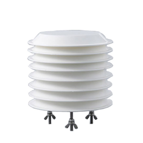 Combined air temperature and relative humidity sensor
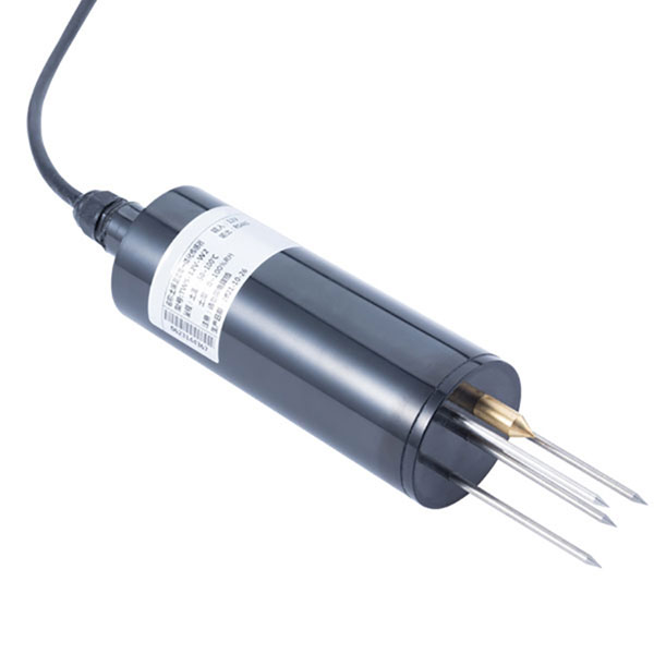 TDR Soil Moisture & Temperature Sensor for irrigation| RS485 |4-20mA| NBL-S-THR
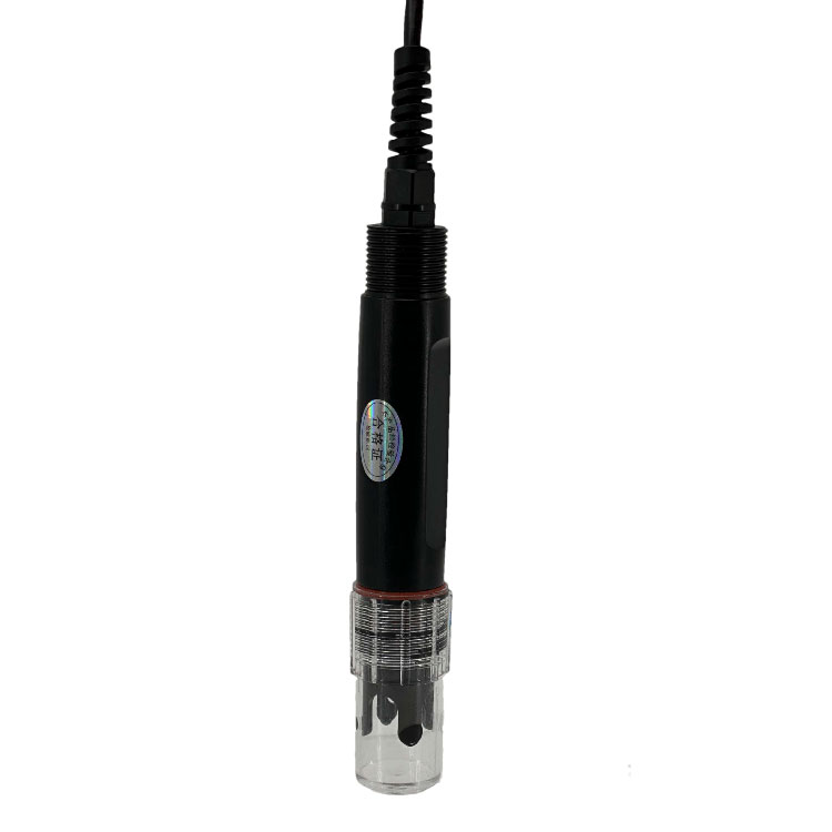 Soil pH sensor RS485 soil Testing instrument soil ph meter for agriculture |NBL-S-PH
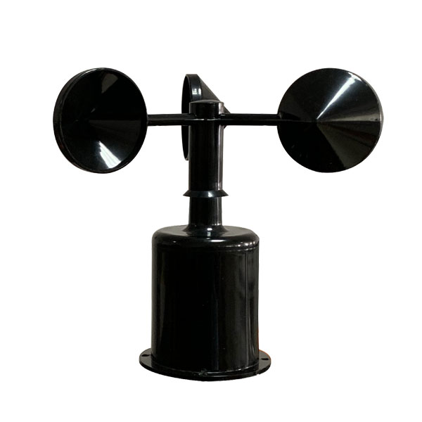 Wind Speed sensor Output Modbus/RS485/Analog/0-5V/4-20mA
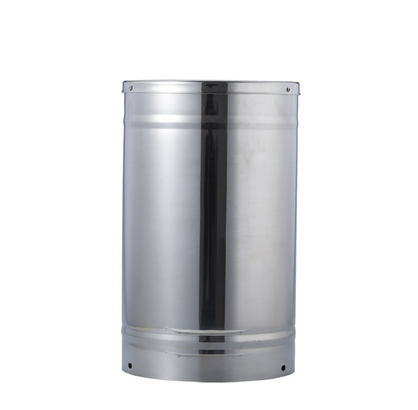 Tipping bucket rain gauge for weather monitoring auto rainfall sensor RS485/Outdoor/stainless steel
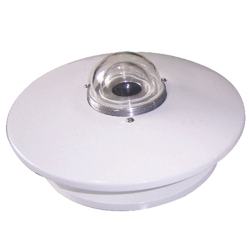 Pyranometer Solar Radiation Sensor 4-20mA/RS485


Screenshot, WhatsApp to identify the QR code
WhatsApp number:+8615367865107
(Click on WhatsApp to copy and add friends)