

— Blogs —
—Products—
 Consumer hotline +8618073152920
 WhatsApp:+8615367865107
Address:Room 102, District D, Houhu Industrial Park, Yuelu District, Changsha City, Hunan Province, China
Product knowledge
Time:2025-12-04 11:25:56 Popularity:698
Quick Answer: An ultrasonic weather station for transmission line monitoring measures the local weather around a line corridor. Wind speed, wind direction, air temperature, humidity, pressure and rainfall can support operating assessments, but they do not directly measure conductor temperature, sag, tension or ice thickness. Choose the sensor configuration around the utility's intended decision, then connect it to an approved data logger or RTU with identifiable timestamps and data-quality flags.
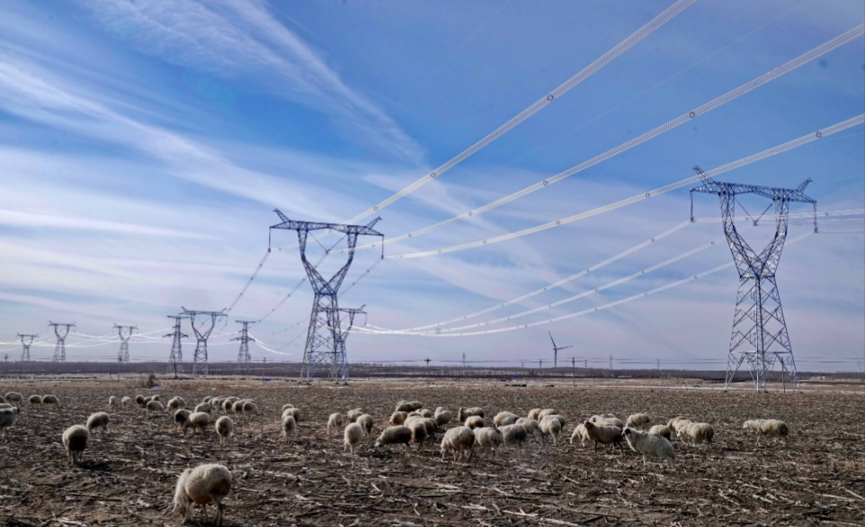
Two line sections a short distance apart can experience different wind exposure. A sheltered valley, exposed crossing and ridge approach should not automatically share one weather observation. The purpose of corridor monitoring is to resolve those local differences sufficiently for the operating task, rather than install the largest available number of meteorological channels on every tower.
For a wind-event investigation, direction relative to the span and short-duration wind variation matter. For a thermal-rating study, the engineering model needs representative cooling conditions, ambient temperature and solar input, together with conductor and electrical information. For an icing investigation, temperature and precipitation provide context, but dedicated icing, conductor or mechanical observations may still be required.
A useful specification therefore names the line sections to be represented, the variables the receiving application actually uses and the required update interval. A weather station can support a utility's assessment; it should not be described as independently preventing galloping, landslides, icing or outages.
Ultrasonic wind measurement compares sound transit times in opposing directions. Airflow produces a difference between the two travel times, and measurements along two axes allow wind speed and direction to be calculated. There are no rotating wind cups or mechanical vane bearings in the ultrasonic measurement path. This removes those particular wear points, not the need for inspection.
Bird activity, contamination, ice, a disturbed acoustic path and movement of the support can still affect observations. A sensor with a low ambient-temperature rating is not automatically a heated or ice-free instrument. Where freezing precipitation is a design condition, specify how icing will be detected, how questionable wind readings will be flagged and whether a different instrument arrangement is needed.
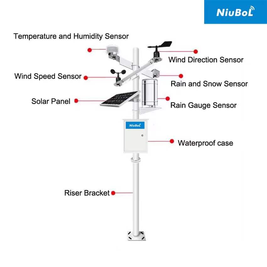
NiuBoL offers integrated sensors and modular weather stations. Integrated construction reduces separate mounting and wiring work; a modular station allows different instruments to occupy different heights or locations. That distinction can matter more than the nominal number of channels where temperature exposure and wind exposure cannot be satisfied at the same point.
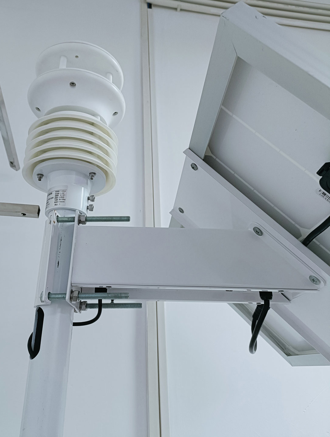
The NBL-W-61GUWS combines six measurements, including piezoelectric rainfall. The following values apply to that model, not to every integrated sensor illustrated on this page. Higher-parameter configurations, including the linked NBL-W-71GUWS, require their own electrical and channel specification.
| Parameter | NBL-W-61GUWS specification | Engineering implication |
|---|---|---|
| Wind speed | 0-60 m/s; accuracy +/-0.3 m/s + 3% FS; resolution 0.01 m/s | Check the full-scale accuracy term against the uncertainty allowed by the operating application. |
| Wind direction | 0-359 degrees; accuracy +/-3 degrees; resolution 1 degree | Record geographic orientation and span bearing in the same reference system. |
| Air temperature | -40 to +80 degrees C; accuracy +/-0.5 degrees C; resolution 0.1 degree C | Ambient air temperature is not conductor temperature. |
| Relative humidity | 0-100% RH; accuracy +/-5% RH; resolution 0.1% RH | Use for local atmospheric context, not direct conductor ice measurement. |
| Barometric pressure | 10-1100 hPa; accuracy +/-1.5 hPa; resolution 0.1 hPa | Distinguish measured station pressure from pressure adjusted to sea level. |
| Rainfall | 0-8 mm/min; accuracy +/-10%; resolution 0.01 mm | Impact-based rainfall is not a measurement of ice loading or snow-water equivalent. |
| Supply and consumption | 12-24 VDC; average 0.4 W without a dust sensor | Budget the logger, modem, battery losses and any additional equipment separately. |
| Communication | RS485, Modbus RTU, 9600 bps | Match the delivered register map and serial settings to the receiving device. |
| Environment | Operating temperature -40 to +80 degrees C; operating humidity 0-95% RH; IP65 | The humidity operating limit is distinct from the RH measurement scale. IP65 does not establish lightning or icing immunity. |
| Cable assembly | Length, jacket material and connector arrangement to be selected for the installation | Specify UV exposure, routing, mechanical support and the required environmental rating at joints. |
Resolution is the smallest reported increment, not measurement uncertainty. In particular, 3% FS must not be silently changed to 3% of the reading. A thermal-rating calculation with tight wind-uncertainty requirements needs an explicit review of that accuracy expression before the sensor is accepted.
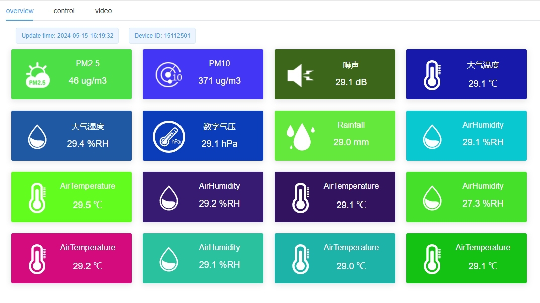
A receiving application needs more than a live number. Store the acquisition time, station identifier, units and validity of each observation. If a radio connection fails, the last received value must not continue to appear as current weather. Local storage and later upload are useful only when the original measurement times remain distinguishable from the upload times.
Wind direction is conventionally the direction from which the wind blows. A northerly wind and a north-south span are therefore not equivalent to crosswind across that span. The line-analysis application must apply its own angle convention correctly. Do not substitute a scalar mean wind speed for a specified gust statistic, or average direction arithmetically across north.
For example, equal observations of 359 and 1 degrees describe wind close to north, not a mean direction of 180 degrees. Use an appropriate circular or vector method, and retain the averaging interval. A dashboard value without this information cannot reliably be compared with another station or an engineering model.
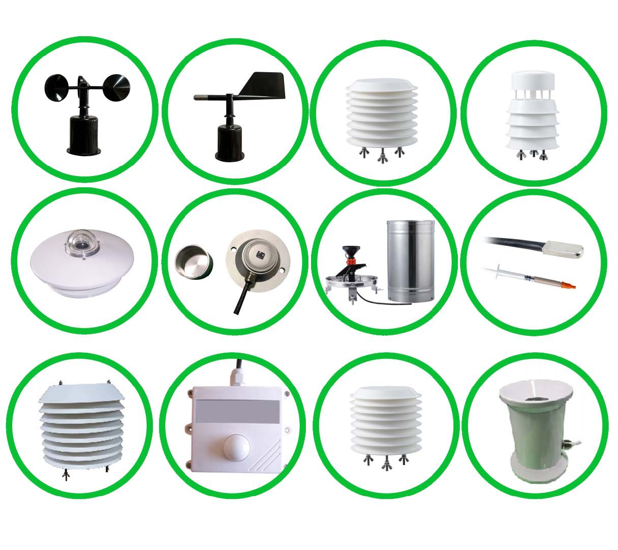
In a modular arrangement, rotating cups measure wind speed and a vane measures wind direction. Those functions should remain distinct in the point list and commissioning records. Separate NBL-W-SS and NBL-W-DS wind sensors are specified as IP65 for new configurations. That rating does not automatically extend to a logger, power controller or exposed cable splice.
A six-parameter unit does not include solar irradiance simply because its enclosure resembles a higher-parameter sensor. If the line-rating method needs solar input, select the required radiation channel or add a suitable pyranometer. Illuminance in lux is not an interchangeable solar-radiation input in W/m2.
For precipitation, choose between compact piezoelectric integration and a separate rain gauge according to the observation requirement. Compare accumulation behavior, exposure and field checks, not only resolution. A collector-free impact sensor still requires a clean sensing surface, while a tipping-bucket installation needs a level collector and inspection for blockage.
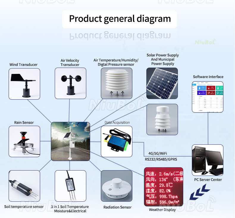
The sensor's local interface is RS485 Modbus RTU. Cellular or other remote connectivity belongs to the selected data logger, RTU or gateway; the serial sensor does not acquire those network functions by itself. The illustrated system arrangements show possible component roles, not a promise that every interface is included in one package.
First prove communication on a controlled bench supply. Read each required channel, check units and signed temperature decoding, and compare the displayed values with the register interpretation. Then test the complete cable and acquisition equipment. Address conflicts, inconsistent serial settings and an unsuitable bus layout can prevent reliable polling even when every device supports Modbus.
Installation on or near transmission assets requires utility-approved electrical, structural and access procedures. Tower grounding, surge paths, isolation, cable routing and permitted mounting positions need project-specific design. Do not use a general weather-station mounting drawing as authorization to attach equipment to energized infrastructure.
Keep signal connections and power entry protected, support cables independently of connectors and assess the complete equipment assembly for its electromagnetic environment. IP65 describes ingress protection; it does not certify a station for a particular substation or transmission-line electromagnetic compatibility requirement.
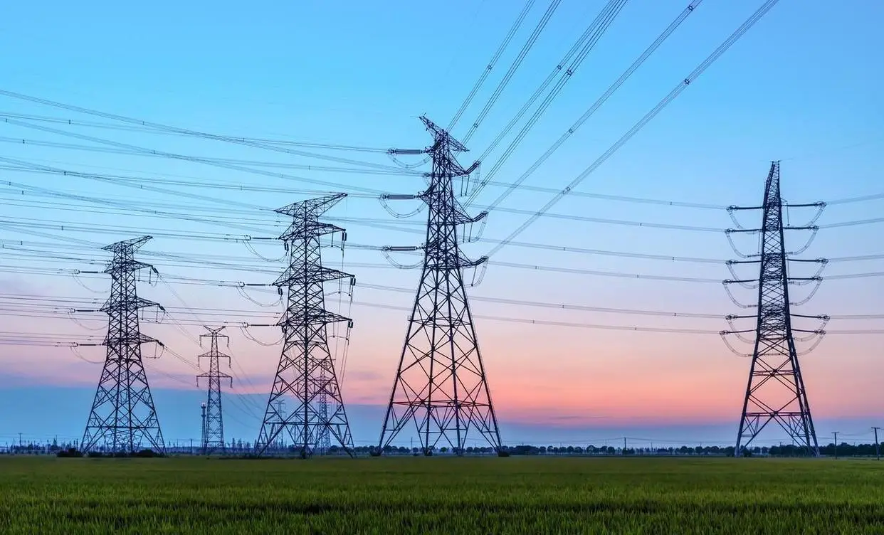
Dynamic line rating considers changing thermal conditions rather than assuming that one fixed weather case applies continuously. Published research on hourly dynamic line ratings describes the role of weather in conductor heat balance. Depending on conditions, the calculated rating may be higher or lower than a static assumption; an increase is not guaranteed.
A weather station alone does not calculate an approved ampacity. Conductor properties, electrical loading, thermal limits, solar conditions and the utility's calculation and validation process are separate requirements. Some implementations also use direct conductor temperature, sag or other line measurements. The limiting section of the circuit must be considered rather than selecting the most favorable station reading.
Mounting a sensor high on a tower can improve access to an exposed airflow but may also place it in a structural wake or away from the conditions at the limiting span. Review wind sectors and terrain with the line engineer. A convenient installation location is not automatically a representative thermal-rating location.
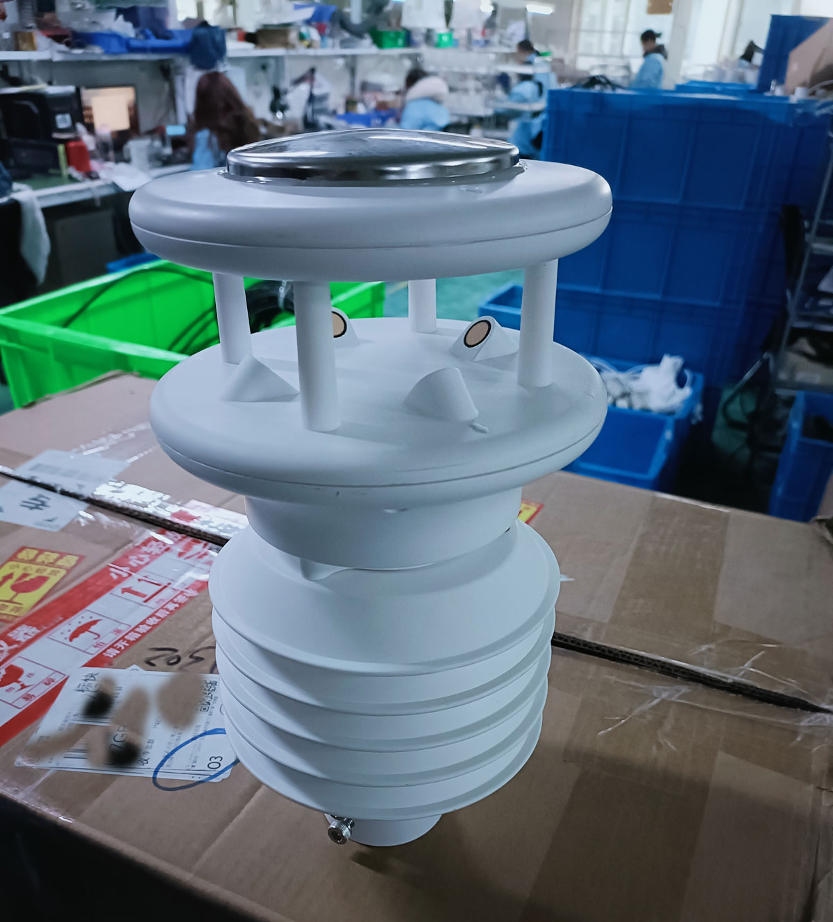
For a quotation, send NiuBoL the intended monitoring task, terrain and mounting constraints, required channels, uncertainty requirement, receiving controller and power arrangement. Identify any need for heating, independent conductor measurements or a dedicated radiation instrument. These choices determine a meaningful system scope more accurately than asking for a universal transmission-line weather station price.
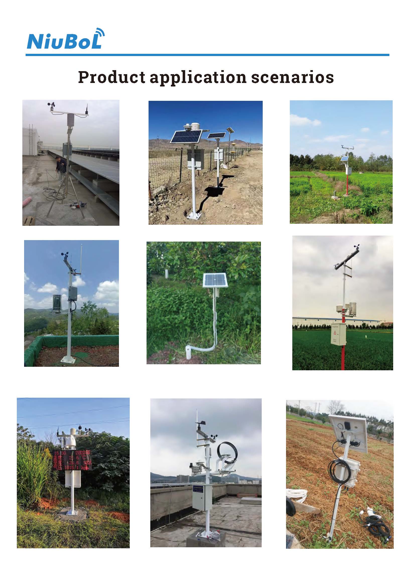
It measures local weather, not conductor ice thickness or mechanical ice load. Temperature, humidity and precipitation can inform an icing assessment, but direct confirmation requires an appropriate additional measurement or validated utility method.
No. Its six channels are wind speed, wind direction, temperature, humidity, pressure and rainfall. Add a suitable radiation instrument or select a different configuration when irradiance is a required input.
Resolution alone cannot establish suitability. Review the accuracy expression, mounting exposure, averaging method and the line model's allowed uncertainty. A finely displayed reading can still carry a larger measurement error.
A compatible RS485 Modbus RTU master can read the sensor when the electrical interface, serial settings and register interpretation match. The utility's isolation, cybersecurity and telemetry requirements remain separate integration checks.
No. An ambient operating-temperature range does not establish de-icing performance. Specify freezing-precipitation exposure and the treatment of obstructed or invalid wind readings before ordering.
Use terrain, exposure changes, critical spans and the operational analysis to define the network. There is no defensible universal station spacing or monitoring radius for every corridor.
Identify the sensor variant, acquisition unit, remote communication, power system, mounting, cable assembly and any required surge or isolation equipment. State separately whether installation engineering and direct line measurements are included.
An ultrasonic weather station for transmission line monitoring is useful when its location and output match a defined corridor decision. Select a model with suitable uncertainty, verify wind direction and time handling, and keep local weather distinct from direct conductor measurements. NiuBoL can configure the sensing and acquisition equipment around the line engineer's channel list and installation conditions.
Prev:Definition and Core Value of Small Automatic Weather Stations
Next:Forest Fire Weather Station Readings: Humidity, Rain and Wind
Related recommendations
Sensors & Weather Stations Catalog
 Agriculture Sensors and Weather Stations Catalog-NiuBoL.pdf
Weather Stations Catalog-NiuBoL.pdf
Agriculture Sensors Catalog-NiuBoL.pdf
Water Quality Sensor Catalog-NiuBoL.pdf
Related products
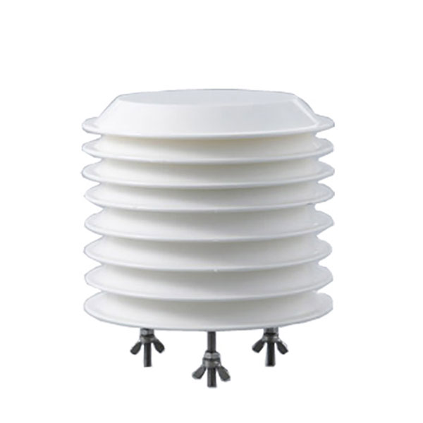 Combined air temperature and relative humidity sensor
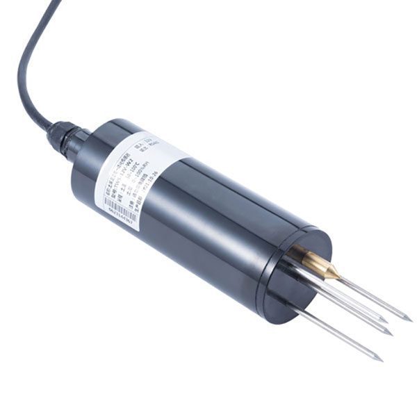 TDR Soil Moisture & Temperature Sensor for irrigation| RS485 |4-20mA| NBL-S-THR
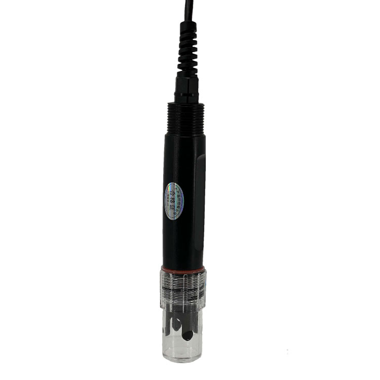 Soil pH sensor RS485 soil Testing instrument soil ph meter for agriculture |NBL-S-PH
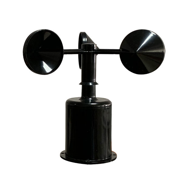 Wind Speed sensor Output Modbus/RS485/Analog/0-5V/4-20mA
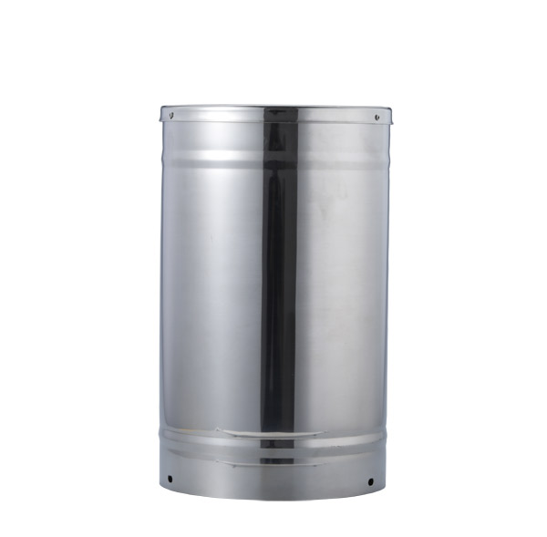 Tipping bucket rain gauge for weather monitoring auto rainfall sensor RS485/Outdoor/stainless steel
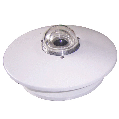 Pyranometer Solar Radiation Sensor 4-20mA/RS485

Screenshot, WhatsApp to identify the QR code
WhatsApp number:+8615367865107
(Click on WhatsApp to copy and add friends)