

— Blogs —
—Products—
 Consumer hotline +8618073152920
WhatsApp:+8615367865107
Address:Room 102, District D, Houhu Industrial Park, Yuelu District, Changsha City, Hunan Province, China
Product knowledge
Time:2026-09-23 10:00:00 Popularity:188
An aquaculture water quality monitoring system should distinguish loss of monitoring power from loss of aeration power. A battery-backed logger can remain online while the aerators have stopped. Conversely, working aerators do not prove that a valid oxygen measurement is reaching the operator. Design power-state feedback, pond-specific measurements and the approved response as separate functions.
Draw the supply paths for the sensors, acquisition equipment, network device, aerator controls and aerator motors. Mark shared supplies and protective devices. If a single DC supply serves every probe, one fault can remove several observations; if the same mains circuit supplies monitoring and aeration, a power interruption may remove the warning at the moment it is most useful.
A backup battery for instruments is not a backup supply for motors. Keep their ratings and autonomy calculations separate. Identify what the farm can still observe, communicate and operate after each supply is lost. The resulting design may require local operating procedures as well as hardware; an additional sensor alone cannot restore stopped aeration.
| Condition | What the system knows | Response to define |
|---|---|---|
| Monitoring remains online; aerator supply is lost | Water readings may continue while oxygen delivery has changed. | Raise a power/equipment alarm and initiate the farm's approved backup action. |
| Aerator command is on; running feedback is absent | The command has not established actual equipment operation. | Check the starter, protection and permitted running feedback rather than trusting the command bit. |
| DO input becomes unavailable | The current oxygen condition is not established by that channel. | Use the approved unavailable-input procedure; do not substitute a healthy-looking value. |
| Network fails; field acquisition continues | Local observations may exist but the remote team may not receive them. | Use supported local indication or alarm arrangements and retain a communication-failure warning. |
A DO probe measures oxygen at its sensing point. It does not measure motor current, shaft rotation or delivered airflow. An electrical running indication also does not prove that oxygen is distributed usefully throughout the pond. Retain both water and equipment observations where the operating decision needs them.
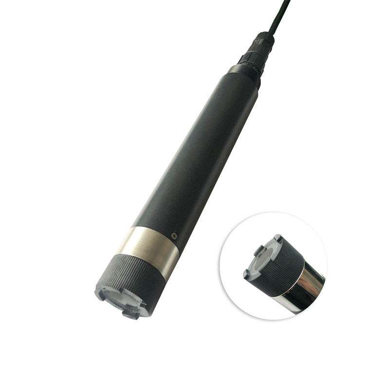
The NiuBoL NBL-WQ-DO optical probe can provide the oxygen channel through RS485 Modbus RTU. Assign its location and depth to the actual pond. A value near a bubble plume or a sheltered edge should not automatically control equipment for an entire pond without a location assessment.
For several ponds on one monitoring station, associate each valid DO observation with its own equipment and alarm destination. A shared logger must not turn one available pond reading into an apparently healthy status for all ponds. The pond monitoring and alarm guide covers measuring-point selection; here, the additional task is to preserve the distinction during power and equipment faults.
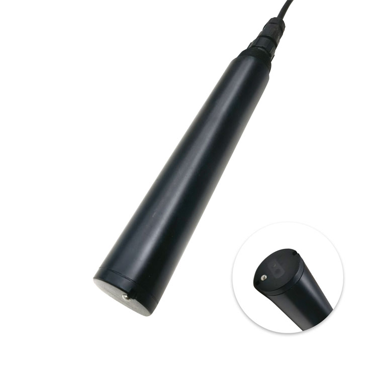
Turbidity can be a useful separate water observation. The following TS probe is not the DO instrument or an aerator-status detector. Include it where particle information serves a defined farm decision, rather than treating all water-quality channels as interchangeable oxygen protection.
| NiuBoL configuration | Relevant specification | Power-loss planning consequence |
|---|---|---|
| NBL-WQ-DO measurement | 0–20 mg/L; ±2% FS; resolution 0.01 mg/L | The full-scale error term is ±0.4 mg/L; do not set close operating bands from resolution alone. |
| Base DO supply and exposure | 12–24 VDC; below 0.3 W at 12 V; 0–45 °C; pressure <0.2 MPa; IP68 | Keep the probe operating envelope separate from cabinet and network hardware. |
| Base DO construction | POM/316L; 3/4 NPT immersion mounting; standard 5 m cable | Specify cable jacket, protected joints and retrieval without cable tension. |
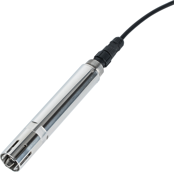
| NBL-WQ-NHN-4S | 0–100.00 or 0–1000.0 mg/L; 12–24 VDC; 0.2 W at 12 V; RS485 Modbus RTU | This is a separate ammonium-selective channel, not a redundant oxygen input. |
| NHN-4S conditions | 0–40 °C; pH 4–10; pressure <0.1 MPa; POM/316L; IP68; standard 5 m cable | Approve the actual water matrix and low-level performance before adding it to the farm package. |
| MPS-5B alternative assembly | Up to 6 parameters including temperature; 12 VDC; 2 W at 12 V | Do not size an integrated assembly as a loose low-power probe or assume it includes ammonia. |
For a simple planning example, allow 0.3 W for a base DO probe and 0.2 W for an NHN-4S. Their combined allowance is 0.5 W, or 12 Wh over 24 hours. This is a sensor-only calculation, not battery sizing or an autonomy claim. The logger, modem, regulators, losses and any cleaning equipment remain additional loads, and starting requirements need separate verification.
An ammonia observation must retain its reporting basis and actual matrix limitations. NHN-4S accuracy includes an absolute ±1 mg/L term, so it should not be approved for every low-concentration farm alarm simply because it displays two decimal places. It is not automatically an un-ionized NH3 toxicity measurement.
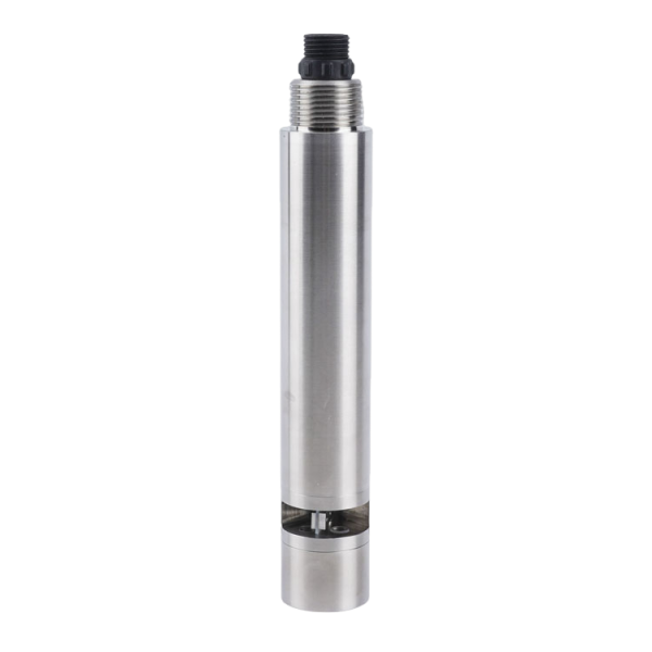
The COD instrument below belongs to a different measurement task. An organic-load observation may support investigation of changing source water or waste loading, but it does not establish the pond's present DO or whether an aerator is running. Keep its range, method and operating interpretation separate from oxygen response logic.
The receiving PLC or RTU should distinguish a valid low DO result, unavailable measurement, lost equipment feedback and failed alarm delivery. These conditions can require different actions. Define the permitted fallback with the responsible farm engineer; neither a default zero nor a retained last value is universally suitable.
Record the age of the last successful observation. If a network reconnects and sends old records, show them as history rather than fresh evidence that the pond has recovered. Equipment command, actual feedback and oxygen response should remain separately visible during restart.
Test the logic through controlled input simulation or a planned test that does not create harmful pond conditions. Check loss of one sensor supply, loss of communications, missing running feedback and restoration after power returns. Measure whether the designated operator actually receives the message and knows which pond and equipment it concerns.
For a NiuBoL system inquiry, provide the pond layout, actual sensor locations, aerator-control interface, available running feedback and backup arrangements. Separate the required sensor package from motor controls and emergency power. This makes the quotation reflect what the system must observe during a failure.
Not unless a separately designed power system supplies those loads. Instrument backup and motor backup are different electrical duties and need separate sizing and protection.
No. DO describes local water conditions. Confirm equipment operation with appropriate feedback, then assess whether the resulting water response is adequate for the operating plan.
Not automatically. Define the response around each pond's equipment, available backup and staffing. Record which action is allowed when the oxygen value itself is unavailable.
No. Integration changes shared failure and retrieval boundaries. Review what happens to all channels when the assembly supply, cable or common body is taken out of service.
Demonstrate pond identity, valid DO interpretation, equipment feedback, alarm delivery and recovery from the selected fault scenarios. A normal live dashboard alone does not establish those functions.
An aquaculture water quality monitoring system becomes more useful when it explains what has failed as well as what the water reads. Separate sensor power, aeration power, command and running feedback. Verify the pond-specific response and complete power budget before treating a connected station as operational protection.
Related recommendations
Sensors & Weather Stations Catalog
 Agriculture Sensors and Weather Stations Catalog-NiuBoL.pdf
Weather Stations Catalog-NiuBoL.pdf
Agriculture Sensors Catalog-NiuBoL.pdf
Water Quality Sensor Catalog-NiuBoL.pdf
Related products
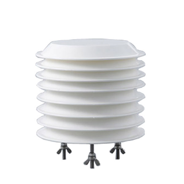 Combined air temperature and relative humidity sensor
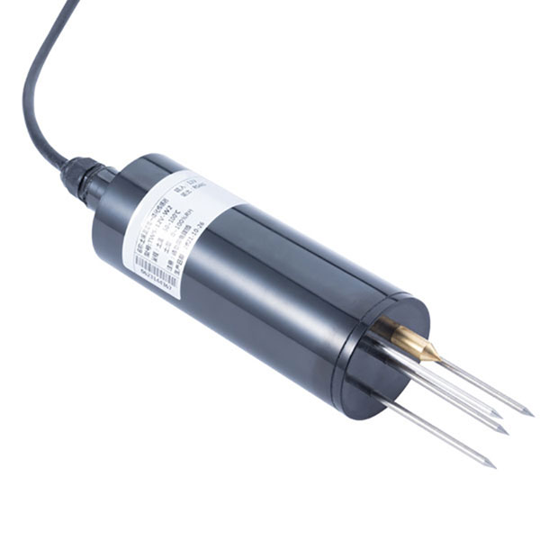 TDR Soil Moisture & Temperature Sensor for irrigation| RS485 |4-20mA| NBL-S-THR
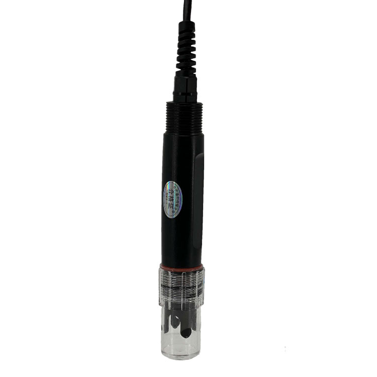 Soil pH sensor RS485 soil Testing instrument soil ph meter for agriculture |NBL-S-PH
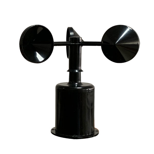 Wind Speed sensor Output Modbus/RS485/Analog/0-5V/4-20mA
 Tipping bucket rain gauge for weather monitoring auto rainfall sensor RS485/Outdoor/stainless steel
 Pyranometer Solar Radiation Sensor 4-20mA/RS485


Screenshot, WhatsApp to identify the QR code
WhatsApp number:+8615367865107
(Click on WhatsApp to copy and add friends)