





— Blogs —
—Products—
 Consumer hotline +8618073152920
WhatsApp:+8615367865107
Address:Room 102, District D, Houhu Industrial Park, Yuelu District, Changsha City, Hunan Province, China
Product knowledge
Time:2024-12-24 15:53:59 Popularity:10508
Automatic irrigation with soil moisture sensors needs a watering strategy as well as a start threshold. Continuous watering can suit a zone where infiltration and root-zone response are understood. Pulse-and-soak operation divides the dose into shorter applications with pauses for infiltration and observation. Neither method should keep a valve open indefinitely while waiting for one buried probe to respond.
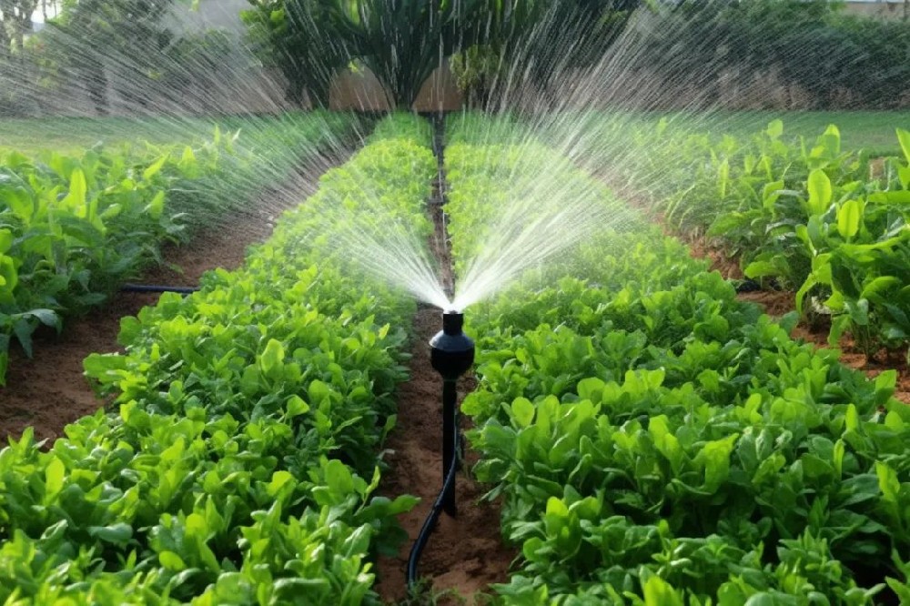
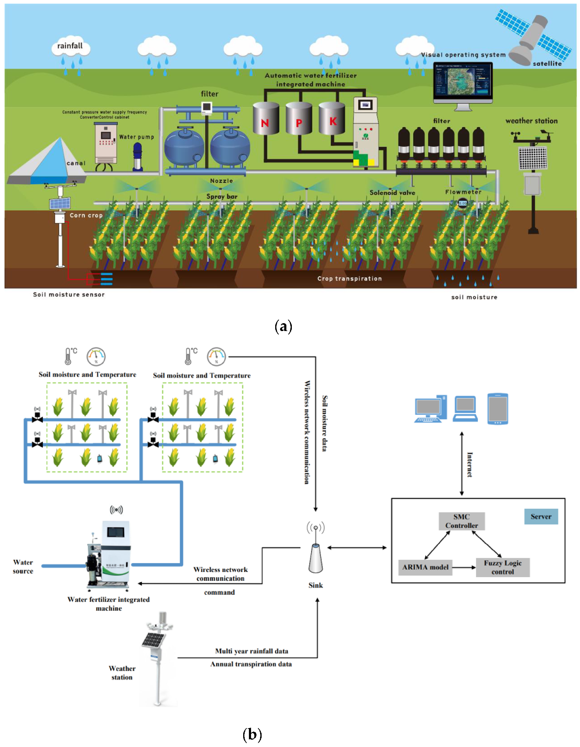
A soil probe measures conditions around its electrodes. The controller decides whether watering is permitted, and the pump, valves and distribution network deliver water. A communications module makes records or commands accessible; it does not establish that water reached the roots. An automatic irrigation system needs all these functions to work together.
The basic feedback sequence remains useful: observe the soil, compare a valid reading with an appropriate trigger, apply water and assess the response. The missing detail is what happens between opening the valve and seeing a change at the probe. Water needs time to reach the measuring depth, and the first wet spot may not represent the whole irrigated zone.
For a field contractor, this distinction affects both the equipment scope and commissioning. Include the sensor input, decision logic, actuator interface and evidence of water delivery. A moisture sensor is not a pump starter, and its signal output must not be treated as a power output for a solenoid or motor.
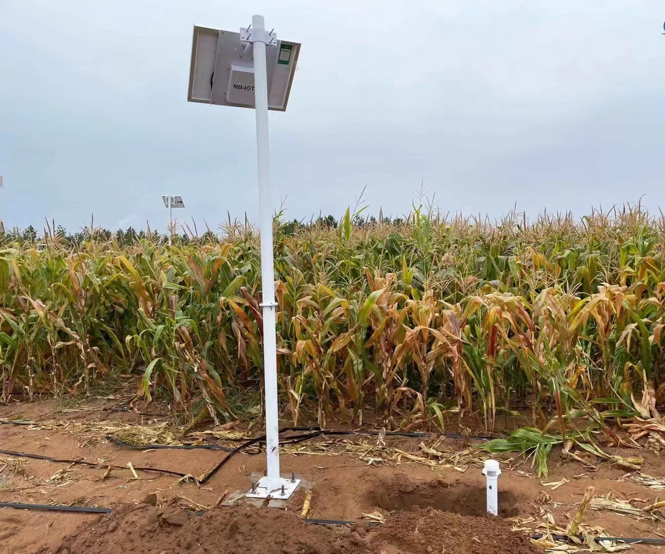
A probe below the surface may remain unchanged while the upper soil wets. With drip irrigation, the wetting pattern also depends on distance from the emitter. A delayed response can therefore be a physical transport effect rather than a failed sensor. Conversely, a probe directly beside an emitter can respond before the wider root zone receives the intended dose.
Check actual delivery and sensor placement before extending the run. A closed isolation valve, blocked emitter or wrong zone assignment can produce the same flat moisture trace. The soil moisture profile interpretation guide discusses wetting and drying patterns; use that evidence to distinguish a delayed response from a delivery problem.
| Operating approach | Where it can help | What must be checked |
|---|---|---|
| Continuous application | A measured application can infiltrate without unacceptable ponding or runoff | Application rate, dose limit, distribution and the delay to the measuring depth |
| Pulse-and-soak | Pauses are needed to let applied water infiltrate or to observe redistribution | Pulse volume, pause duration, accumulated dose and post-pause response |
| Monitoring without automatic actuation | The response is not yet understood or the water network is not ready for unattended control | A responsible operator and a defined trial before enabling automatic watering |
Pulse-and-soak is not a universal improvement over continuous watering. Short cycles can be unsuitable for some pumps or valves, while an excessive pause may interrupt an application unnecessarily. Choose the sequence from the soil, crop, irrigation equipment and observed response, not from the availability of a timer setting in an app.
Start with a supervised trial in a defined zone. Record the initial moisture, emitter or sprinkler operating condition, application duration and any available flow total. Observe the surface and the relevant root-zone depth during watering and after the valve closes. Repeat under representative conditions before relying on one event to set the sequence.
For pulse operation, keep the delivered dose across all pulses visible. Do not reset the application limit after each pause and thereby permit an unlimited succession of small doses. During a soak period the valve is closed; the controller waits for the intended assessment time before deciding whether another application is allowed.
A useful sequence has an independent maximum dose or run time, an appropriate restart condition and a response to missing or invalid measurements. Those limits are determined for the site. There is no defensible universal moisture percentage, five-minute pulse or fixed soak duration that suits every crop, soil and distribution system.
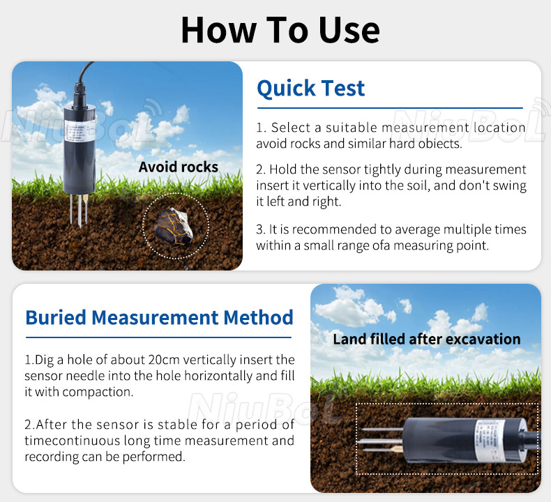
Choose depth and position from the active root zone and irrigation pattern. Avoid an air gap around the electrodes and do not force a probe into stones. For buried monitoring, restore contact with the surrounding soil without creating a preferential water path along the cable or excavation. A convenient shallow installation can become a surface-wetting indicator rather than the intended root-zone feedback.
Distinguish a quick insertion test from a permanent control point. Moving a probe between locations changes the observation represented by its reading. If soil texture or irrigation distribution varies substantially, check whether separate zones or additional observations are needed instead of assuming one point describes an entire field.
The NiuBoL NBL-S-THR soil temperature and moisture sensor measures soil dielectric properties to derive a moisture reading. It is not a simple resistance switch. Its temperature measuring range and operating environment are separate specifications; the wider measuring scale must not be presented as a guarantee of operation over that entire scale.
| NBL-S-THR item | Specification | Meaning for the irrigation controller |
|---|---|---|
| Soil moisture channel | 0-100%; resolution 0.1%; stated accuracy +/-3% | Check response in the actual soil before setting action levels; display increments do not define a suitable crop threshold |
| Temperature measurement | -50 to 100 C; resolution 0.1 C; accuracy +/-0.5 C | A measurement scale, not the equipment operating-temperature rating |
| Operating environment | -40 to 80 C | Assess the installation against this limit separately |
| Supply and power | DC 12-24 V; approximately 0.3 W | Budget sensor power separately from valve, pump, logger and communications loads |
| Output options and protection | RS485 Modbus RTU, 4-20 mA or 0-5 V version; IP68 | Order the version matching the receiver; do not assume all outputs are supplied together |

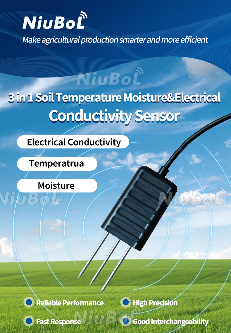
The NBL-S-TMC three-in-one soil sensor adds electrical conductivity to temperature and moisture. That can be relevant to a fertigation investigation, but conductivity is not a direct measurement of irrigation dose or individual nutrient concentration. Adding channels does not resolve a badly placed moisture point.
Use the actual delivered sensor's register map or analog scaling at the PLC, RTU or irrigation controller. For the NBL-S-THR RS485 version, readings are scaled by ten and an invalid/missing indication must not become a valid dry-soil value. Check serial settings and communication spacing against the supplied configuration before enabling control.
Show whether the zone is waiting, watering, soaking, complete or held for a fault. A soil trend alone does not explain these states. Keep valve commands separate from any available flow or pressure confirmation, and retain the total application across interruptions. A remote display should not show a commanded watering state as proof of delivered water.
If a connection fails during a soak period, the local controller needs an agreed response. It must not repeatedly restart the sequence simply because the dashboard reconnects. Define who can resume the zone after a delivery fault and whether the unfinished dose should be continued or cancelled.

In a greenhouse, the relevant observation may be a particular bed or substrate zone rather than the whole structure. In an orchard, emitter spacing and root distribution affect the feedback point. In landscaped grounds or a sports surface, runoff and sprinkler distribution may be central to the trial. Keep these physical differences in the control design instead of copying one threshold between projects.
Send NiuBoL the soil or substrate, crop and root-zone depth, irrigation method, intended observation points and controller inputs when requesting sensors. Include the desired control sequence and available evidence of delivery. Compare the complete installation scope rather than assume a soil probe alone includes automatic valves, a pump controller or remote control software.

No. A local rise may show that water reached one point, not that the intended root zone received the required application. Assess the response alongside placement, dose and the operating limits established during the trial.
No. It can help manage infiltration and observation delays in suitable conditions, but savings depend on the starting practice, distribution and chosen sequence. Verify delivered volumes and soil response rather than promise a fixed saving.
No. A missing, stale or invalid reading must be handled separately. Treating it as dryness can start unnecessary watering and defeat the dose limit.
No. Hysteresis separates decision thresholds to limit repeated switching near one value. A soak period is a valve-off interval that allows water movement and assessment. A project may need both, with different purposes.
Demonstrate the correct zone opening, bounded application, valve-off pause where used, valid moisture response and the response to a failed input or delivery fault. Include the complete cycle rather than test only a displayed percentage.
Not without checking it. Soil texture, structure, roots and application pattern change infiltration and the probe response. Reassess the trial and limits when those conditions change.
Automatic irrigation with soil moisture sensors works through a defined relationship between measurement, water delivery and time. Select continuous or pulse-and-soak operation from the actual wetting response, keep the total dose bounded and distinguish an invalid reading from a genuine need for water. The sensor specification supports that design; it does not supply the irrigation strategy by itself.
NBL-S-THR soil temperature and moisture sensor instruction manual.

NBL-S-TMC soil temperature, moisture and conductivity sensor document.
NBL-S-TM soil temperature and moisture sensor instruction manual.
NBL-S-TMCS soil temperature, moisture, conductivity and salinity sensor document.
Prev:Indoor vs Outdoor Weather Station: Separate Sensors, Shared Logger
Next:Noise and Dust Monitoring Station Placement: Shared Mast or Separate Points?
Related recommendations
Sensors & Weather Stations Catalog
 Agriculture Sensors and Weather Stations Catalog-NiuBoL.pdf
Weather Stations Catalog-NiuBoL.pdf
Agriculture Sensors Catalog-NiuBoL.pdf
Water Quality Sensor Catalog-NiuBoL.pdf
Related products
 Combined air temperature and relative humidity sensor
 TDR Soil Moisture & Temperature Sensor for irrigation| RS485 |4-20mA| NBL-S-THR
 Soil pH sensor RS485 soil Testing instrument soil ph meter for agriculture |NBL-S-PH
 Wind Speed sensor Output Modbus/RS485/Analog/0-5V/4-20mA
 Tipping bucket rain gauge for weather monitoring auto rainfall sensor RS485/Outdoor/stainless steel
 Pyranometer Solar Radiation Sensor 4-20mA/RS485


Screenshot, WhatsApp to identify the QR code
WhatsApp number:+8615367865107
(Click on WhatsApp to copy and add friends)

