





— Blogs —
—Products—
 Consumer hotline +8618073152920
WhatsApp:+8615367865107
Address:Room 102, District D, Houhu Industrial Park, Yuelu District, Changsha City, Hunan Province, China
Product knowledge
Time:2025-01-07 20:03:05 Popularity:2434
Noise and dust monitoring station placement should follow what each channel must represent. A shared mast can simplify power and communications, but the microphone, particulate inlet and wind sensors may need different exposure or service access. Use separate measuring points when one location cannot meet those requirements. A common dashboard does not require every sensor to occupy the same physical point.
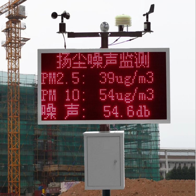
A construction-site boundary check, an industrial-site trend and a neighbourhood environmental observation are different tasks. Identify the area and sources the measurements are intended to represent before choosing a convenient mast location. A location beside a generator, wall or vehicle route can be useful for one question and misleading for another.
Do not assume that installing a monitoring station establishes regulatory conformity or occupational exposure. The required method, acoustic descriptor, particulate fraction, location and supporting documents need assessment for the intended use. A general environmental microphone and an optical PM channel do not automatically provide every measurement needed by every reporting scheme.
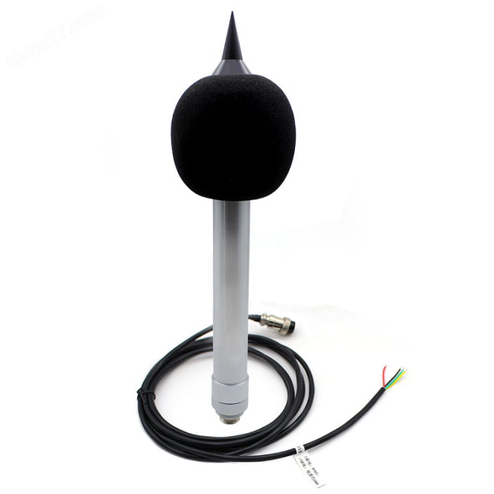
The NiuBoL NBL-W-NS measures sound level using a condenser microphone. Its placement should consider nearby reflective surfaces, screening structures and sound generated by station equipment. Do not move the microphone behind a cabinet simply to protect the cable if the cabinet changes the sound field being observed.
A fan, loose panel or vibrating structure near the microphone can contribute to the measured sound. Check for those local sources during commissioning. The sensor is a numerical sound-level instrument, not an audio recorder; a dB value alone does not identify which machine or activity caused it.
The NBL-W-PM uses fan-assisted laser scattering to estimate PM2.5 and PM10 mass concentrations. The inlet must encounter the air relevant to the task. A sheltered pocket behind a wall, a concentrated exhaust plume or splash from nearby suppression equipment can change what the reading represents.
Keep the sampling path accessible for inspection and avoid placing it where routine activities obstruct airflow. The choice is not simply high versus low mounting. It is whether the installed inlet represents the required area and remains usable through the site's operating conditions. Do not transfer a boundary-monitoring interpretation to a point intended to examine a specific local source.
| Component | Relevant specification | Placement implication |
|---|---|---|
| NBL-W-PM particulate sensor | PM2.5: 0-1000 ug/m3; PM10: 0-2000 ug/m3; fan-assisted laser scattering | Provide representative airflow and service access; do not obstruct or expose the inlet to direct spray |
| NBL-W-PM interface and power | RS485 Modbus RTU; DC 12-24 V; approximately 350 mW | Include cable routing and voltage at the selected measuring point |
| NBL-W-NS sound-level sensor | 30-130 dB; 31.5 Hz-8 kHz; 0.5-inch microphone | Assess sound exposure and local station-generated noise separately from PM inlet placement |
| NBL-W-NS output and environment | RS485 Modbus RTU or selected 4-20 mA version; DC 12 V; IP65 | Specify the delivered output and protect installation details without obstructing the microphone |
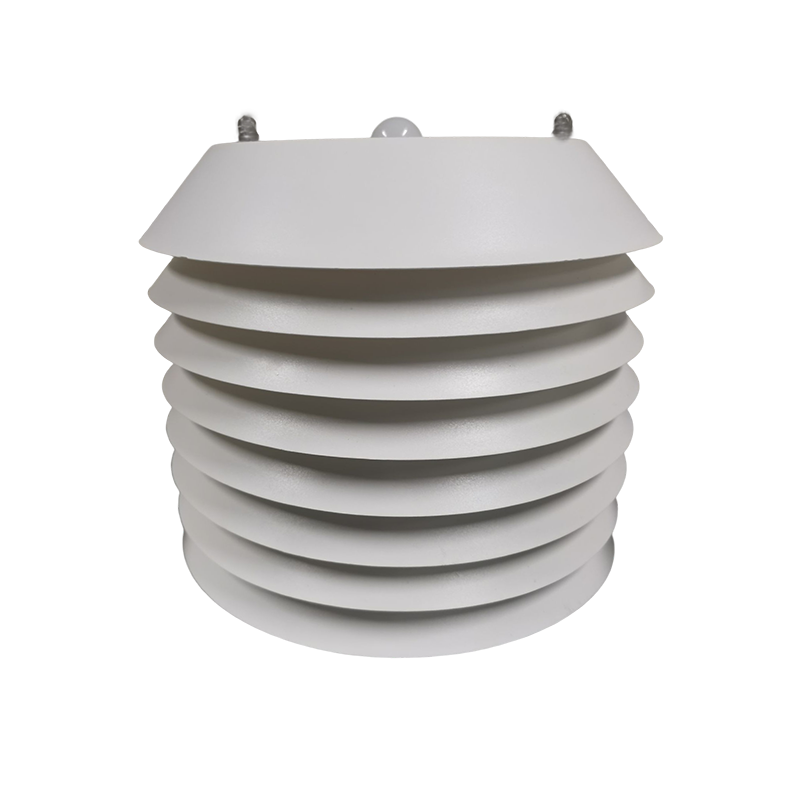
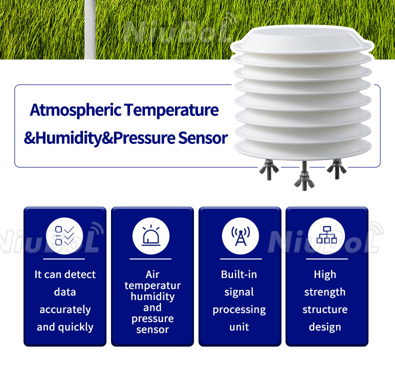
Air temperature, humidity and pressure observations can help interpret site conditions. The NBL-W-LBTH measures atmospheric conditions at its installed exposure. It does not automatically correct an obstructed particulate inlet or remove local acoustic reflections from the noise channel.
For optical PM measurements, humidity and particle properties can affect interpretation. Retain weather observations where they help explain changes, but do not apply an arbitrary correction simply because both channels are available. Any correction method needs a suitable basis for the actual sensor and aerosol conditions.
Wind instruments need an exposure that supports the intended wind observation. A sheltered location chosen for a microphone or cabinet may not describe air movement over the area being investigated. Likewise, wind measured on an open mast should not be assumed identical to the air movement within a screened or enclosed work area.
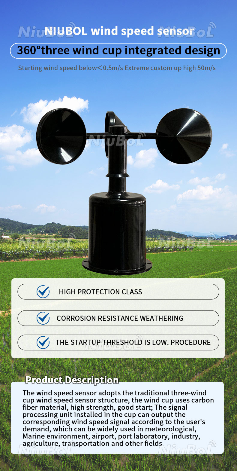
The NBL-W-SS cup wind-speed sensor and NBL-W-DS direction sensor are IP65 devices. Their protection rating does not remove the need to assess obstructions, vibration and safe service access. Wind direction can support event interpretation, but it does not uniquely establish that a particular activity caused a PM or noise change.
A shared structure can suit a site where all required observation positions can be accommodated without obstructing sensors or introducing significant local interference. It can reduce duplicated power and networking equipment and make a compact installation easier to service. Check the actual geometry, not just a drawing that places every sensor on one crossarm.
During inspection, run the station with its display, fans and other accessories active. Listen for loose or vibrating parts near the microphone, inspect the PM inlet and review whether brackets or the panel obstruct wind or radiation shielding. Resolve the interference at the installation rather than hide it with a dashboard offset.
Separate the channels where their intended locations cannot be reconciled. A microphone may need a position different from the particulate inlet; wind context may come from a more open exposure. The separation should answer a specific measurement problem, not create extra stations without a defined purpose.
Keep each channel's physical location identifiable in the report. A PM observation and a sound-level observation from different points may still be useful together, but they should not be presented as though both were made at one identical coordinate. Record height, exposure and subsequent moves to the extent needed by the project method.
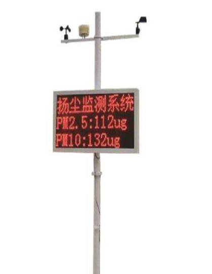
A PLC, RTU or data logger can collect compatible instruments from different measuring positions. For RS485 Modbus RTU channels, verify addresses, serial settings, register scaling and cable design. Where supply voltages differ, check them at the actual sensor ends rather than assume one power output suits every component.
Keep numeric sound levels, PM concentrations and weather channels clearly labelled with their units and observation times. A common upload does not mean identical sampling or averaging periods. If one device fails, mark that channel unavailable without discarding or falsely refreshing unrelated measurements.
Provide NiuBoL with a site layout, the required observation points and the intended reporting quantities when requesting a configuration. Ask whether a shared structure is suitable or whether compatible separate sensors would answer the task more clearly. Price the measuring arrangement that meets the need, not merely the most compact cabinet-and-display assembly.
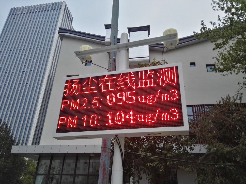
No. They may share a structure where their exposure requirements can both be met. Use separate points when local airflow, sound reflections, station noise or the intended monitoring locations make one mast unsuitable.
It can contribute local sound depending on the arrangement. Check the complete operating assembly, including loose panels and accessories, rather than assessing the microphone with all nearby equipment switched off.
No. The optical channel measures particle-related conditions at its inlet. Use site activity, wind, measurement validity and appropriate additional investigation before assigning the observation to a source.
Not automatically. Weather channels provide context. They do not remove a physical obstruction, eliminate acoustic reflections or establish a valid correction model for every aerosol and installation.
Yes, where their interfaces, power, acquisition and data interpretation are supported. Retain the separate locations and observation periods; one platform does not make the measurements physically colocated.
Settle the purpose, required measurement quantities, observation locations and reporting expectations. Then specify the sensor versions, mounting, cable routes, power and acquisition scope for a comparable equipment offer.
Noise and dust monitoring station placement is a channel-by-channel measurement decision. Share a mast where it works, and separate the points where exposure or local interference requires it. Preserve each location and measurement meaning when integrating the values into a common reporting system.
Prev:Automatic Irrigation with Soil Moisture Sensors: Continuous or Pulse-and-Soak?
Next:EC sensor for soil
Related recommendations
Sensors & Weather Stations Catalog
 Agriculture Sensors and Weather Stations Catalog-NiuBoL.pdf
Weather Stations Catalog-NiuBoL.pdf
Agriculture Sensors Catalog-NiuBoL.pdf
Water Quality Sensor Catalog-NiuBoL.pdf
Related products
 Combined air temperature and relative humidity sensor
 TDR Soil Moisture & Temperature Sensor for irrigation| RS485 |4-20mA| NBL-S-THR
 Soil pH sensor RS485 soil Testing instrument soil ph meter for agriculture |NBL-S-PH
 Wind Speed sensor Output Modbus/RS485/Analog/0-5V/4-20mA
 Tipping bucket rain gauge for weather monitoring auto rainfall sensor RS485/Outdoor/stainless steel
 Pyranometer Solar Radiation Sensor 4-20mA/RS485


Screenshot, WhatsApp to identify the QR code
WhatsApp number:+8615367865107
(Click on WhatsApp to copy and add friends)

