





— Blogs —
—Products—
 Consumer hotline +8618073152920
WhatsApp:+8615367865107
Address:Room 102, District D, Houhu Industrial Park, Yuelu District, Changsha City, Hunan Province, China
Product knowledge
Time:2025-09-07 11:26:22 Popularity:1130
Quick Answer: Agriculture sensors work by converting a physical or chemical response into a measurement signal. A soil probe may infer water content from dielectric behavior, a cup anemometer responds to airflow, and a tipping-bucket rain gauge counts collected water. The important procurement distinction is whether a channel measures the required variable directly or estimates it through a calibration model.
For an engineer evaluating agriculture sensors, the useful sequence is: field condition, sensing element, conversion, compensation, output and interpretation. A digital number at the end of this chain is not automatically a direct measurement of the crop response. Soil moisture does not measure irrigation demand by itself, and air humidity does not measure leaf wetness.
Consider a moisture reading transmitted to a farm controller. The probe responds to an electrical property of the surrounding soil. Its electronics convert that response using a calibration relationship. The controller then reads a scaled value, associates it with a depth and location, and applies a rule. A correct communication packet cannot compensate for an air gap around the probe or an unsuitable calibration.
Water changes the dielectric properties of soil. Dielectric soil moisture sensors use that change to estimate volumetric water content. Different instruments use different excitation and processing methods; capacitance, frequency-domain and time-domain techniques should not be treated as interchangeable names for one circuit.
The NiuBoL NBL-S-THR combines soil moisture and temperature measurement and uses a time-domain reflectometry approach for moisture. The NBL-S-TMCS four-parameter soil sensor uses a frequency-domain approach for moisture and an AC bridge method for conductivity. Choose between them by the required channels and the soil conditions, not simply by the number of values in a data frame.

Soil texture, bulk density, salinity and probe contact can alter the relationship between the electrical response and the reported moisture value. A probe installed in a disturbed planting hole may respond differently from one in an undisturbed root zone. Establish a local baseline after installation, compare wetting and drying behavior, and retain the installation depth with the record.
For irrigation control, compare measurements at representative depths and positions relative to the emitter. A shallow sensor can show rapid wetting while the lower root zone remains dry. The practical decision is whether the monitored volume represents the crop's active roots, rather than whether the instrument produces a smoothly changing chart.
Electrical conductivity reflects the ability of the soil medium to conduct current. It responds to dissolved ions collectively and is affected by water content and temperature. It does not identify a particular nutrient. A conductivity increase after fertilization cannot, on its own, establish the separate nitrogen, phosphorus and potassium concentrations available to a crop.
The NBL-S-TMC-7 integrated soil sensor provides moisture, temperature, conductivity, pH and NPK channels. Its NPK values use empirical coefficients derived from soil electrical characteristics. They are suitable for field reference and trend comparison, not as a replacement for laboratory nutrient analysis. Its integrated pH channel also has lower accuracy than a dedicated glass-electrode method.
This distinction changes the specification. If a project needs repeated relative observations at many farm locations, an integrated probe may reduce installation work. If fertilizer dosing or a contractual soil assessment requires method-specific nutrient results, specify the sampling and analytical method separately. More reported channels do not remove that requirement.
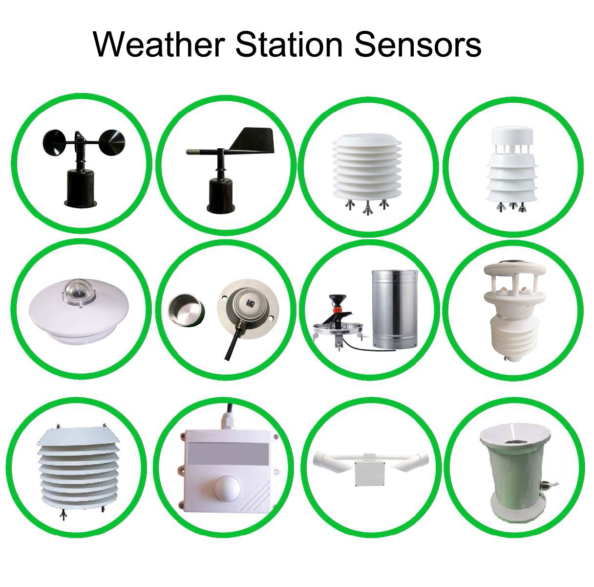
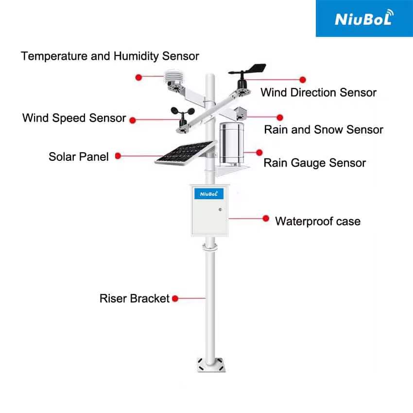
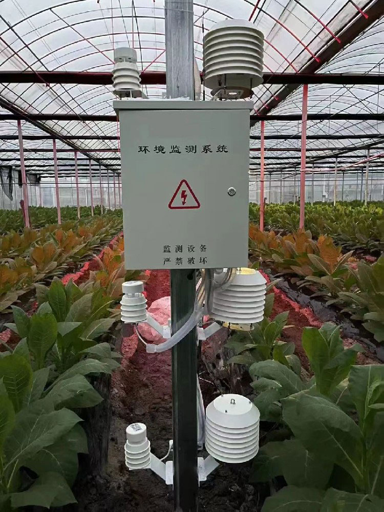
A louvered air sensor combines environmental channels in a radiation shield. The shield reduces direct solar exposure while allowing ventilation; it does not turn a shaded, poorly ventilated mounting position into a representative field location. The NBL-W-LBTH measures air temperature, relative humidity and atmospheric pressure. Those channels describe the surrounding air, not the temperature of a leaf, fruit surface or sunlit equipment enclosure.
Mechanical wind sensors use the movement of cups or a vane. The NBL-W-SS measures wind speed through cup rotation; a separate direction sensor is needed when the project also requires wind direction. Ultrasonic wind sensors use differences in acoustic transit time along measurement paths. They do not calculate horizontal wind from an echo bouncing back from the crop canopy.
A tipping-bucket rain gauge works differently again. Water collected by its funnel fills a calibrated bucket; each tip represents a defined rainfall increment. The NBL-W-RS configuration with 0.2 mm resolution generates one increment per tip. Blockage, a tilted collector or an incorrectly configured pulse counter changes the reported rainfall even when the electronic connection remains healthy.
Rainfall at the station is not the same as irrigation water reaching each root zone. Wind exposure, canopy interception, runoff and soil infiltration all affect that relationship. Use rainfall as an input to the water-management decision, and use soil observations to check the resulting wetting pattern.
| Sensor example | Published characteristic | Engineering consequence |
|---|---|---|
| NBL-W-LBTH | Air temperature -40 to 80 degree C; accuracy +/-0.5 degree C; 12-24 V DC | Check exposure and shielding as well as the temperature specification. |
| NBL-W-SS | Wind speed range 0-45 m/s or 0-70 m/s; IP65; analog, pulse or RS485 versions | Select the actual range and electrical version before specifying the logger input. |
| NBL-W-RS | 0.2 mm resolution; 0-50 degree C working temperature; pulse, voltage or RS485 output options | Match the counter configuration and assess freezing conditions separately. |
| NBL-S-TMC-7 | 5-24 V DC; RS485 Modbus RTU; default 9600 bps | Check the register definitions and retain the limitations of the estimated nutrient channels. |
These are model-specific examples, not a common specification for all agriculture sensors. Output options are alternatives to select, not a promise that every connector carries all listed signals simultaneously. A usable order identifies the model, channel set, power and output version together.
RS485 describes an electrical interface. Modbus RTU defines serial message framing and transactions. The receiving PLC, RTU or data logger still needs the device address, register map, scaling, data type and channel meaning. Two devices using RS485 can remain incompatible if one uses another protocol or requires different serial settings.
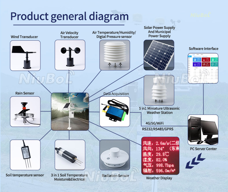
Keep field acquisition separate from backhaul. A cellular modem or wireless gateway can transfer readings onward, but it does not automatically interpret a probe register or supply a missing pulse input. For a mixed weather station, list each sensor's output beside the matching logger input, then test one real value and one disconnected-sensor condition.
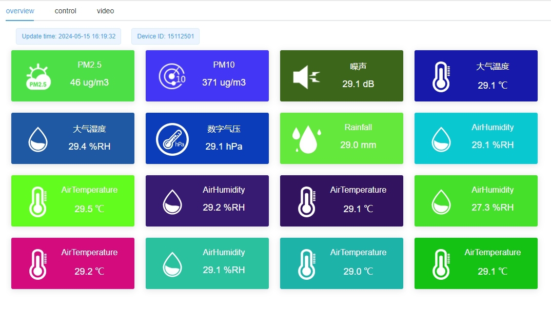
A dashboard should retain units, channel names, timestamps and quality flags. Do not silently repeat the last good value when a sensor stops responding. The image below illustrates a display layout, not a set of measured results for a particular project.
For soil probes, inspect contact and compare the response before and after a known wetting event at the monitored depth. For air sensors, compare readings in the same exposure rather than comparing a shaded field sensor with a sunlit handheld instrument. For a cup anemometer, check free rotation and the configured conversion; spinning the cups proves activity, not wind-speed accuracy.
For a rain gauge, verify level, funnel cleanliness and the specified pulse-to-rainfall factor. A test pulse checks the logger's count path; a controlled water test checks the collector and mechanism as well. Keep these tests separate so a successful electrical simulation is not mistaken for a successful rainfall measurement test.
A multi-parameter probe can reduce cable runs and give several observations at one location. It also places those channels in the same small soil volume. That is useful for relating moisture and conductivity locally, but it does not replace a spatial sampling plan. Select the locations first, then decide whether separate or integrated probes suit the required measurements.
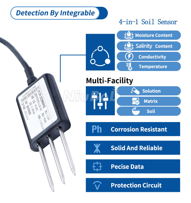
Conductivity alone cannot distinguish individual nutrient ions. Where a device derives NPK estimates from electrical characteristics, use the results within that stated method's limitations. For nutrient-specific decisions requiring analytical accuracy, include laboratory testing and a suitable sampling plan.
No. Confirm Modbus RTU support, serial settings, register addresses, scaling and data types on both sides. If a sensor uses pulse or analog output instead, the controller needs the corresponding input hardware and conversion settings.
One sensor represents its local exposure. Low-lying areas, canopy positions and sheltered sections may differ. Define whether the decision concerns standard air conditions or crop-level conditions, then select the number and location of measurement points accordingly.
No. Ultrasonic wind measurement determines airflow from acoustic transit times. A tipping-bucket rain gauge measures collected precipitation increments. A combined station may contain both functions, but they remain separate measurements with separate installation checks.
Provide the variables required, soil or air measurement locations, operating conditions, controller model, available power and required output. For estimated nutrient channels, describe the intended decision so the measurement method can be evaluated before the configuration is quoted.
For a NiuBoL configuration review, an irrigation project benefits from emitter positions and probe depths; a weather project benefits from the available mast position and surrounding obstructions. These details help select measurements rather than simply increasing the channel count.
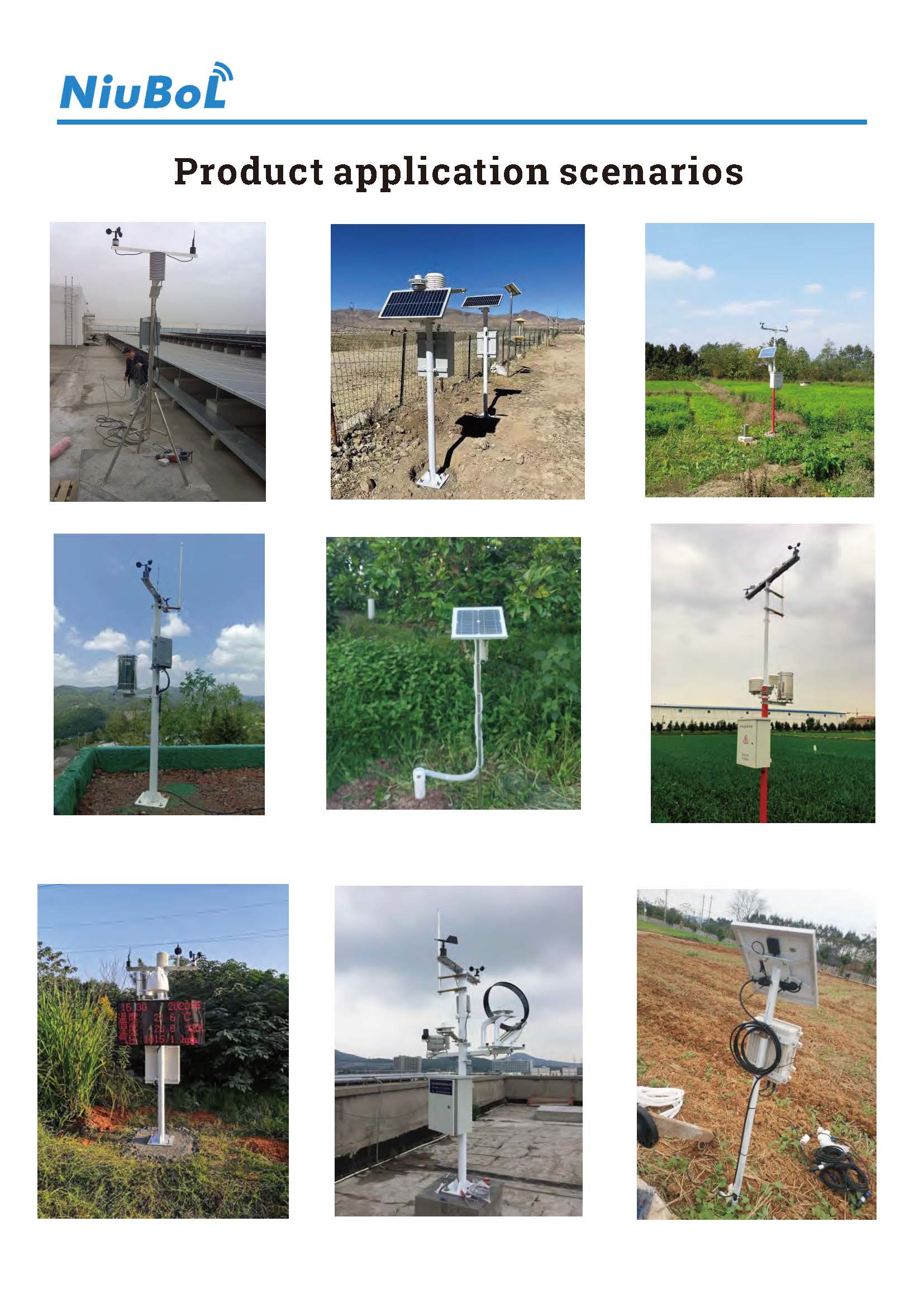
Agriculture sensors work through different physical and chemical mechanisms, and their outputs require different interpretations. Select the measurement principle for the decision, check its field limitations, and then confirm the electrical and communication path. NiuBoL can match soil and weather channels to a defined installation without treating every reported value as a laboratory result.
Prev:Weather Station Total Cost of Ownership: Compare Installed Scope
Next:Agrometeorological Stations: Choose Measurements for Farm Decisions
Related recommendations
Sensors & Weather Stations Catalog
 Agriculture Sensors and Weather Stations Catalog-NiuBoL.pdf
Weather Stations Catalog-NiuBoL.pdf
Agriculture Sensors Catalog-NiuBoL.pdf
Water Quality Sensor Catalog-NiuBoL.pdf
Related products
 Combined air temperature and relative humidity sensor
 TDR Soil Moisture & Temperature Sensor for irrigation| RS485 |4-20mA| NBL-S-THR
 Soil pH sensor RS485 soil Testing instrument soil ph meter for agriculture |NBL-S-PH
 Wind Speed sensor Output Modbus/RS485/Analog/0-5V/4-20mA
 Tipping bucket rain gauge for weather monitoring auto rainfall sensor RS485/Outdoor/stainless steel
 Pyranometer Solar Radiation Sensor 4-20mA/RS485


Screenshot, WhatsApp to identify the QR code
WhatsApp number:+8615367865107
(Click on WhatsApp to copy and add friends)

