





— Blogs —
—Products—
 Consumer hotline +8618073152920
WhatsApp:+8615367865107
Address:Room 102, District D, Houhu Industrial Park, Yuelu District, Changsha City, Hunan Province, China
Product knowledge
Time:2024-09-16 20:17:56 Popularity:2490
To read a soil moisture sensor with a multimeter, first identify whether the delivered sensor has a voltage, current or digital output. A compatible meter can check an analog signal, which must then be converted using that model's scale. It cannot decode RS485 Modbus RTU data into moisture by measuring the voltage between A and B. An electrical reading also does not establish that the probe represents the surrounding soil correctly.
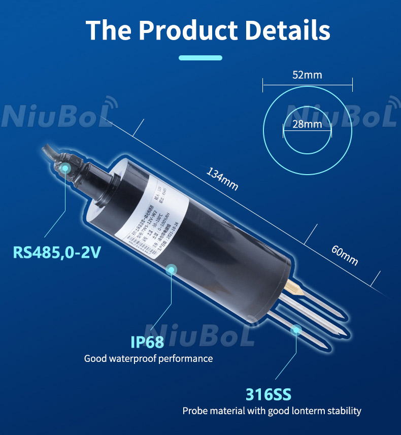
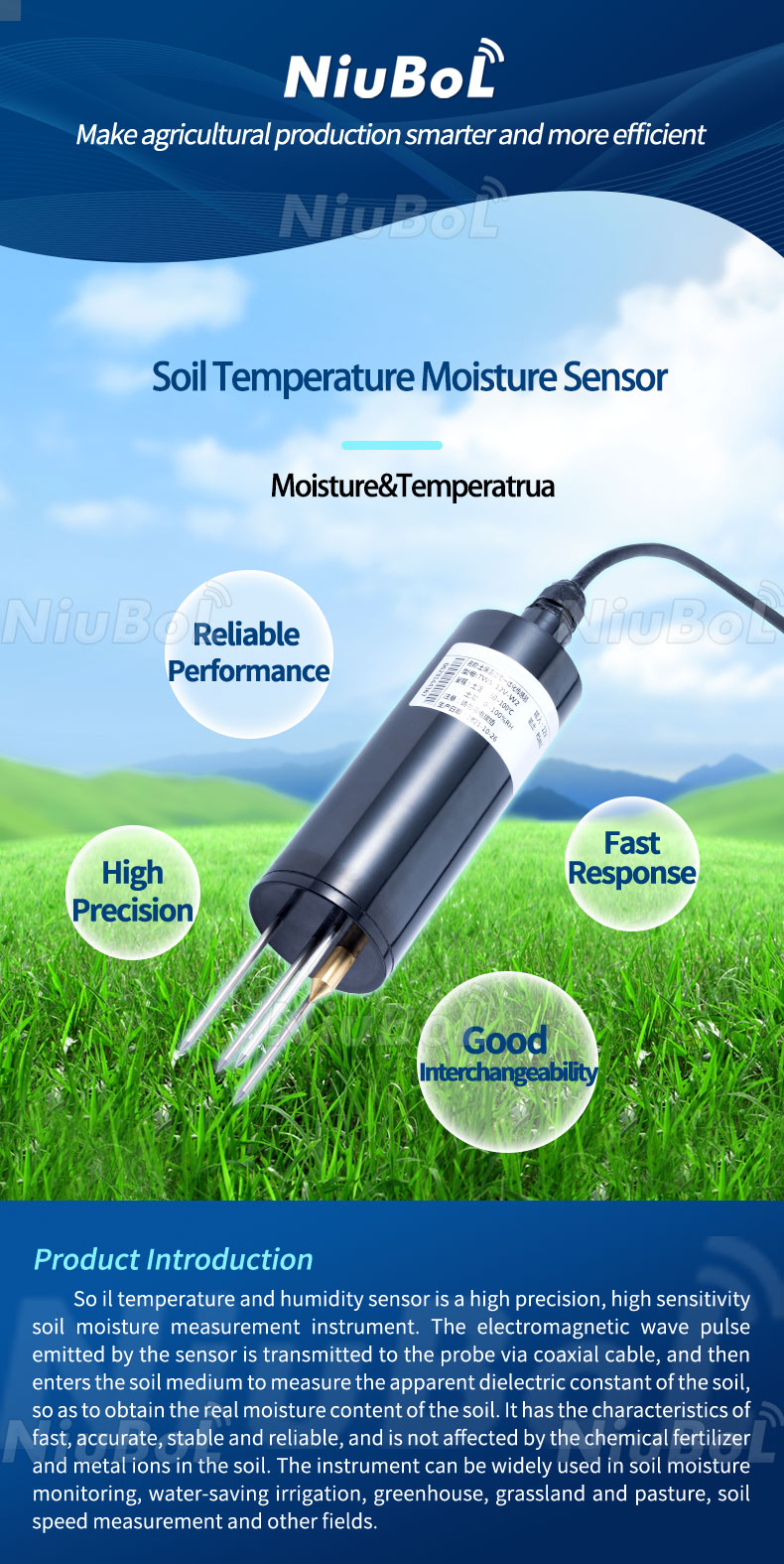
The NiuBoL NBL-S-THR is available with RS485, 4–20 mA or 0–5 V output. These are alternative electrical configurations; do not assume a single unit provides all three outputs. Check the delivered model and wiring diagram. Do not infer the output from the shape of the round probe or the colours shown in a different sensor's illustration.
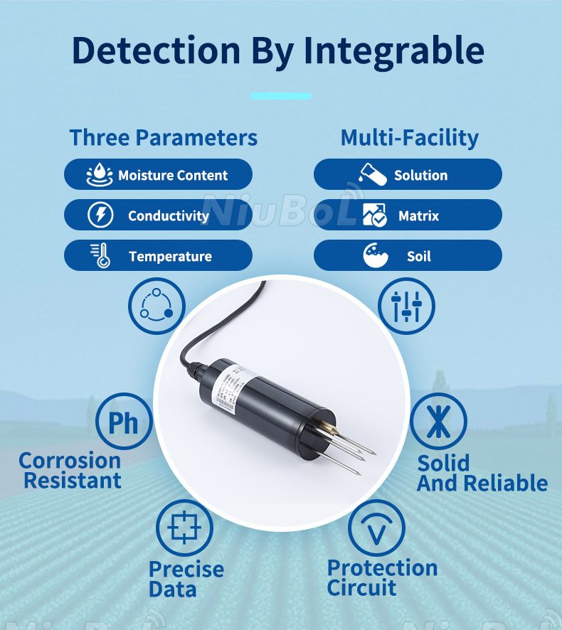
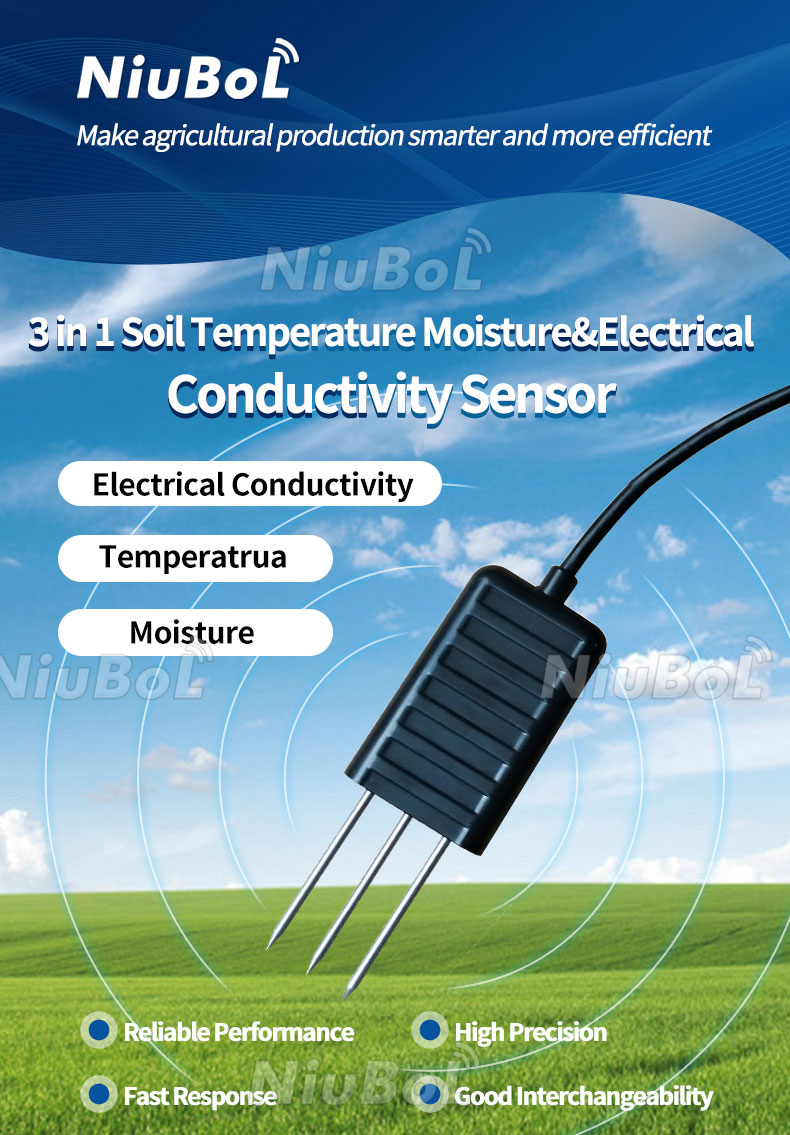
The THR measures soil moisture and temperature. The NBL-S-TMC adds soil EC and uses RS485 Modbus RTU. A picture mentioning three quantities does not give a two-channel THR a conductivity output. Identify both the electrical version and the quantity on each signal wire.
| Delivered output | Useful measuring method | Limit of that check |
|---|---|---|
| 0–5 V analog | Measure DC voltage against the specified signal reference with a compatible high-impedance input. | The value needs the correct moisture or temperature conversion. |
| Three-wire 4–20 mA analog | Use an appropriately rated current measurement arrangement following the output wiring diagram. | It is not automatically wired like a two-wire loop-powered transmitter. |
| RS485 Modbus RTU | Use a suitable RS485 reader or data logger with the device protocol. | A multimeter cannot turn bus voltage into a moisture percentage. |
The THR supply is 12–24 V DC; this is not the same as its 0–5 V output span. With the power isolated, verify terminal identification and connections against the delivered diagram. Select the appropriate meter function and lead sockets before energising the circuit. An input configured for current must not be placed across the power supply or voltage output as though it were a voltmeter.
Confirm the available supply at the probe during operation. A satisfactory cabinet voltage does not prove adequate voltage at the end of a cable. Keep the supply check, signal measurement and interpretation as separate observations so that a power problem is not mistaken for dry soil.
A 0–5 V transmitter must not be connected directly to an ADC merely because the controller has an analog pin. The receiving input needs the appropriate voltage range, reference and protection or conditioning. Likewise, an RS485 output needs an RS485 interface rather than a general-purpose digital input.
For the THR 0–5 V configuration, the moisture conversion is R = V / 5 × 100%, while the temperature conversion is T = V / 5 × 150 − 50°C. V is the measured signal voltage in volts. These formulas apply to the corresponding THR output configuration, not to every soil sensor or voltage transmitter.
| THR channel | Example electrical value | Converted indication |
|---|---|---|
| Moisture, 0–5 V | 2.0 V | 40% |
| Temperature, 0–5 V | 2.0 V | 10°C |
| Moisture, 4–20 mA | 12 mA | 50% |
| Temperature, 4–20 mA | 12 mA | 25°C |
These are calculated examples, not measurements from a project. The identical voltage can represent different engineering quantities on different outputs. If the value at the logger disagrees with the meter conversion, inspect the assigned channel, input type and span before adjusting the probe calibration.
For the THR three-wire current configuration, moisture is R = (I − 4) / 16 × 100%, and temperature is T = (I − 4) / 16 × 150 − 50°C, where I is in mA. The listed current-output load is ≤250 Ω; the voltage-output load is ≥1 kΩ. Match the receiver and measurement arrangement to the selected output.
A meter used to measure current must be connected through the appropriate current path, not placed across two terminals as for a voltage measurement. If using a resistor and a voltage reading instead, its value, tolerance and effect on the permitted load must be part of the design. Do not add an arbitrary resistor or interrupt an active irrigation input casually to obtain a reading.
The THR moisture channel has a 0–100% range, 0.1% resolution and ±3% stated accuracy. An electrical mid-scale result does not verify that accuracy in soil. Contact, the measured medium and installation position still influence what the probe observes. Its IP68 rating does not establish the protection of a separately made cable joint.
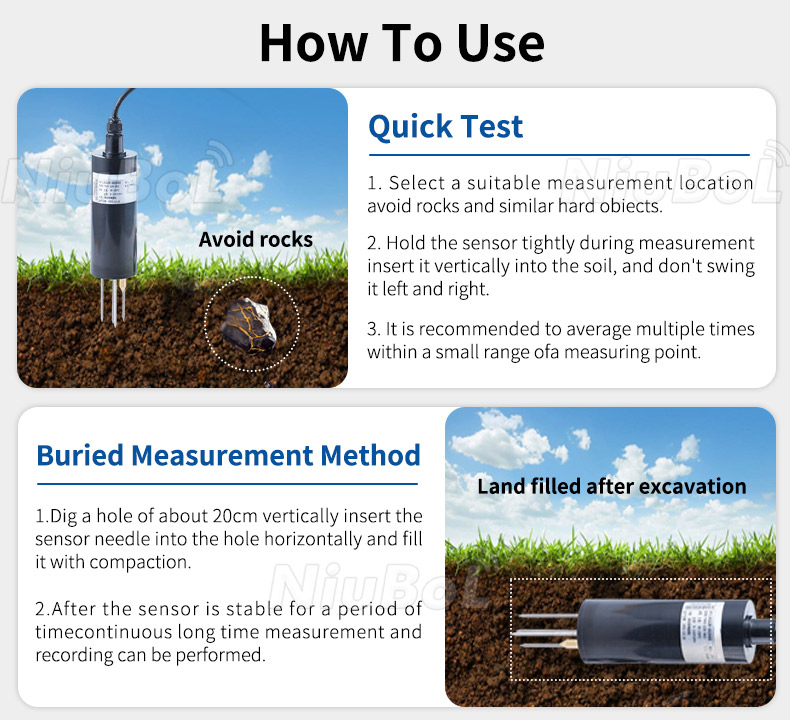
Use representative soil contact and the intended depth when checking response after installation. Do not treat an air reading, a water immersion response or an offset entered to match an unrelated reference as a soil calibration. If the task is absolute water-content verification, use an appropriate soil reference and calibration method.
The installation illustration includes quick insertion and buried arrangements. Choose the arrangement for the required observation rather than treating a fixed illustrated depth as universal. Avoid twisting the probe against stones or leaving voids around the sensing region.
For an RS485 THR or TMC, obtain a correctly decoded reading from a compatible PLC, RTU or data logger. Moisture, temperature and EC need their own units and register interpretation. A valid response is not a reason to apply the analog formulas above to the returned integer.
The soil-sensor integration guide covers decoding and controller validity checks. For the initial meter-based task, first decide whether there is an analog moisture output to measure at all. A digital-only probe needs a different reading tool, not a different multimeter range.
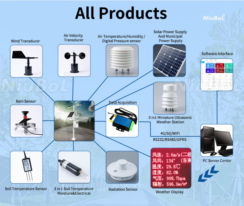
Not by measuring A-to-B voltage. It can assist with suitable electrical checks, but moisture requires protocol communication and decoding with a compatible reader.
Confirm that the wire is the moisture output and that the sensor is the specified 0–5 V version. A THR temperature output at 2 V means 10°C, while its moisture output at 2 V means 40%. Applying the wrong channel conversion can produce a plausible but incorrect result.
Only interpret it through the actual output definition and valid operating condition. A lower-end indication is not proof of representative soil contact or calibration, and a wiring problem must be excluded before using the value for irrigation.
It can support an attended analog check. It does not provide the required unattended record, channel validity or remote access simply by remaining connected. Choose the permanent acquisition equipment for those functions.
Send NiuBoL the delivered model and output version, wiring diagram, supply measured at the probe, meter function, signal value and receiving input configuration. State whether the question is electrical conversion or disagreement with a soil reference; they require different checks.

 NBL-S-THR-Soil-temperature-and-moisture-sensors-Instruction-Manual-V4.0.pdf
NBL-S-TMC-Soil-temperature-and-moisture-conductivity-sensor.pdf
Read a soil moisture sensor by matching the tool to its actual output. For analog THR versions, identify the channel and apply its voltage or current conversion. For RS485 versions, use a protocol-capable reader. Verify the soil measurement separately from the electrical indication.
Prev:How Relative Humidity Sensors Work: Elements, Temperature and Outputs
Next:The Benefits of a Pyranometer for Daily Solar Energy Monitoring
Related recommendations
Sensors & Weather Stations Catalog
 Agriculture Sensors and Weather Stations Catalog-NiuBoL.pdf
Weather Stations Catalog-NiuBoL.pdf
Agriculture Sensors Catalog-NiuBoL.pdf
Water Quality Sensor Catalog-NiuBoL.pdf
Related products
 Combined air temperature and relative humidity sensor
 TDR Soil Moisture & Temperature Sensor for irrigation| RS485 |4-20mA| NBL-S-THR
 Soil pH sensor RS485 soil Testing instrument soil ph meter for agriculture |NBL-S-PH
 Wind Speed sensor Output Modbus/RS485/Analog/0-5V/4-20mA
 Tipping bucket rain gauge for weather monitoring auto rainfall sensor RS485/Outdoor/stainless steel
 Pyranometer Solar Radiation Sensor 4-20mA/RS485


Screenshot, WhatsApp to identify the QR code
WhatsApp number:+8615367865107
(Click on WhatsApp to copy and add friends)

