





— Blogs —
—Products—
 Consumer hotline +8618073152920
WhatsApp:+8615367865107
Address:Room 102, District D, Houhu Industrial Park, Yuelu District, Changsha City, Hunan Province, China
Product knowledge
Time:2026-02-01 10:34:08 Popularity:689
Quick Answer: Irrigation district flow monitoring requires a defensible relationship between velocity, water depth and the wetted channel area. Choose submerged Doppler or non-contact radar equipment after surveying the canal, then verify the installed flow calculation across operating conditions. Remote data transmission is useful only when the underlying measurement and accumulated water volume are valid.
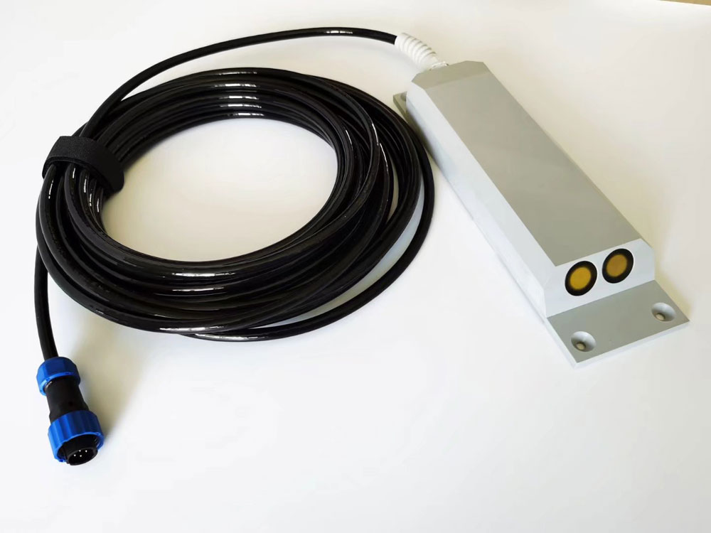
An irrigation renovation project often has existing gates, lined reaches, sediment deposits and seasonal water levels that cannot be treated as identical monitoring sites. Begin with a survey of each proposed measuring section. Record channel geometry, normal and minimum water depth, expected velocity, flow direction, nearby structures and whether water can back up from a downstream gate.
The purpose of the station also matters. An operational trend used to schedule a gate movement may have different verification requirements from a water-allocation total or a quantity used for settlement. Establish the required uncertainty, reference method and data availability before selecting equipment. Do not infer suitability for commercial water accounting from the presence of a cumulative-volume register.
A velocity-area system can sometimes avoid constructing a new weir or flume. That does not mean no civil work or site preparation is needed. A stable mount, surveyed section, protected cable route and safe maintenance access remain necessary. Some locations need a different measuring section because no practical sensor can correct a persistently unsuitable flow pattern.
A submerged ultrasonic Doppler instrument uses reflections from moving particles or bubbles in the water to estimate velocity. It can combine that measurement with pressure-derived depth and a configured channel section. Its suitability depends on adequate acoustic returns, representative flow, sufficient submergence and protection from deposition or debris.
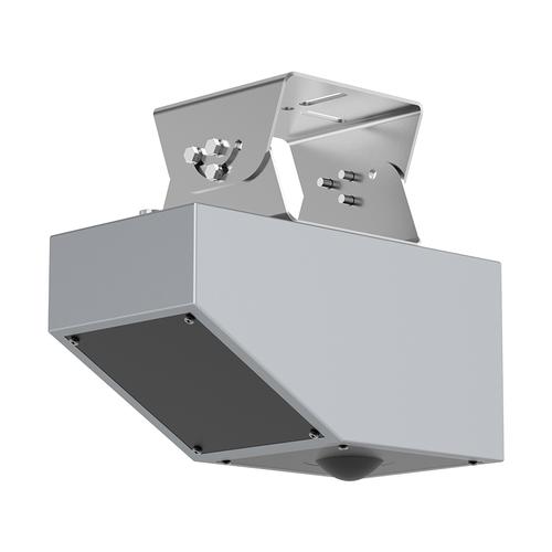
A radar flowmeter measures surface velocity from above the water and combines this with level and section information. Keeping the instrument out of the water reduces direct exposure to fouling and impact, but surface velocity still needs a validated relationship to cross-sectional mean velocity. Wind-driven surface motion, weak surface returns and a changing velocity profile can affect that relationship.
| Site condition | Submerged Doppler consideration | Radar consideration |
|---|---|---|
| Low seasonal depth | The acoustic measuring region must remain adequately submerged | Check velocity sensitivity and whether the measurement footprint remains within flowing water |
| Sediment and debris | Provide clearance, protection and retrieval access without disturbing the measurement | Sensor avoids burial, but deposited sediment still changes the channel area used in the calculation |
| Very clear water | Confirm sufficient acoustic scatterers instead of assuming a usable return | Assess the surface return and actual flow conditions |
| Backwater or reverse flow | Select and test a version that supports the required direction behavior | Check direction handling and the validity of the surface-to-mean relationship |
| Difficult access | Plan a safe method of lifting and cleaning the submerged unit | Allow access to the overhead bracket, antenna and cable connections |
Choose a reach with stable flow rather than the easiest place to attach a bracket. Gate jets, bends, hydraulic jumps, side inflows and pump discharges can produce velocity patterns that a single measurement does not represent. Observe the reach with gates in different normal operating positions, not just during a quiet commissioning visit.
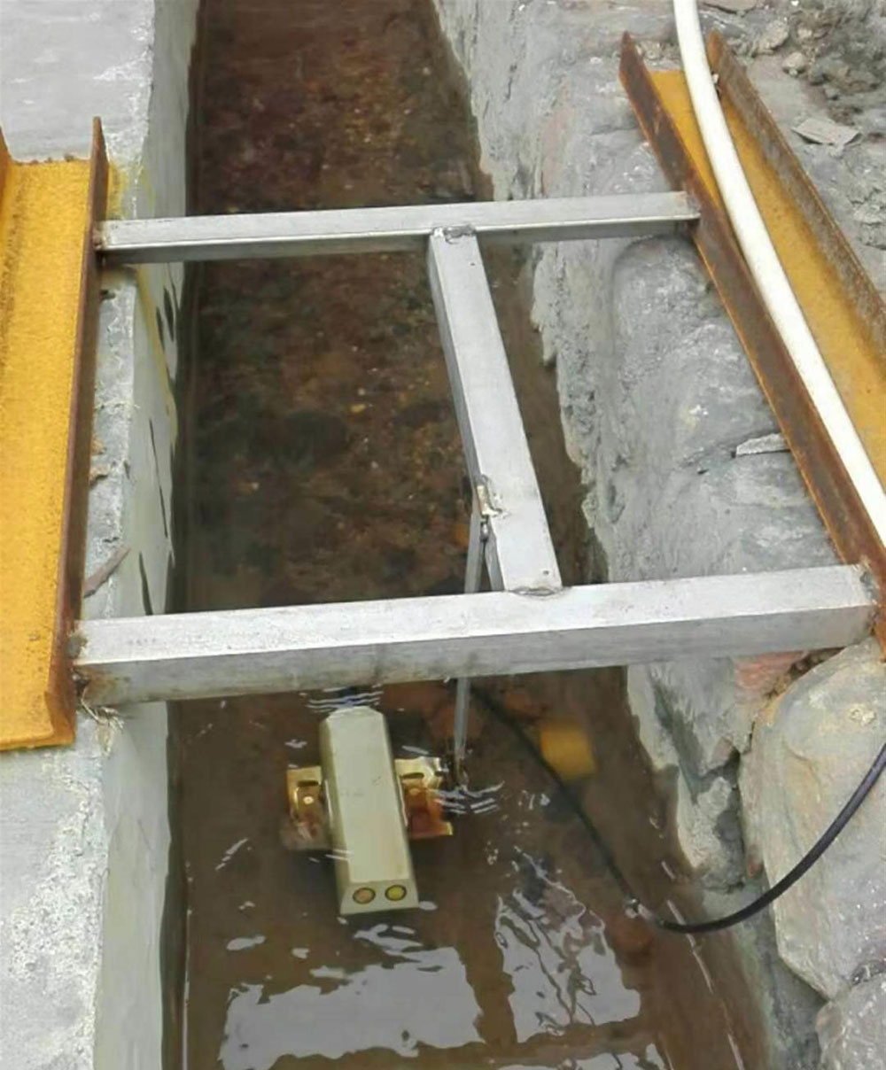
For the NiuBoL unidirectional submerged Doppler arrangement, the sensing face is installed toward upstream flow. A blanket instruction to place the velocity instrument perpendicular to the flow is incorrect. Keep the unit securely fixed and account for its position when interpreting depth. The selected version's required submergence and clear acoustic path must be maintained at the lowest operating level.
A protective barrier can prevent impact but also alter flow or trap debris. Position it according to the installation design and inspect its effect on the measurement area. Do not place a cage directly across the acoustic path and assume the reading is unaffected. The cable also needs restraint so that it cannot pull the instrument out of position.
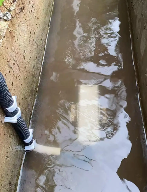
Measure the channel shape at the monitoring location. For a rectangular section, wetted area equals width multiplied by water depth. For a trapezoidal section with bottom width b and side slope z horizontal to one vertical, area is h x (b + z x h). Use the actual section rather than the nominal construction drawing when silt, wear or repairs have changed it.
Store the survey date and level datum with the station configuration. If the bed rises through deposition, an unchanged water-surface level can correspond to a smaller wetted area. Radar does not touch the sediment, but its calculated flow can still be wrong when the configured section is obsolete. Re-survey after material changes rather than trying to correct every discrepancy with a velocity multiplier.
Discharge is Q = A x mean velocity. The instrument's measured velocity may require a site-specific conversion to cross-sectional mean velocity. Establish where that conversion is applied, in the sensor, RTU or server, and avoid applying it twice. A factory coefficient is not evidence that the relationship is correct for every canal.
For a worked example, a rectangular canal 2 m wide with 0.5 m water depth has an area of 1 m2. If its validated mean velocity is 0.6 m/s, discharge is 0.6 m3/s. If that discharge remains constant for one hour, the delivered volume is 2160 m3. This is an arithmetic example, not a claimed performance result for an installation.
When discharge varies, integrate the sequence of time-stamped flow values over their actual intervals. Do not multiply the latest value by an entire day or treat a communication gap as zero flow. If the station retains a cumulative counter, test rollover, reset and power-loss behavior. Keep forward, reverse and net totals distinct where the project needs them.
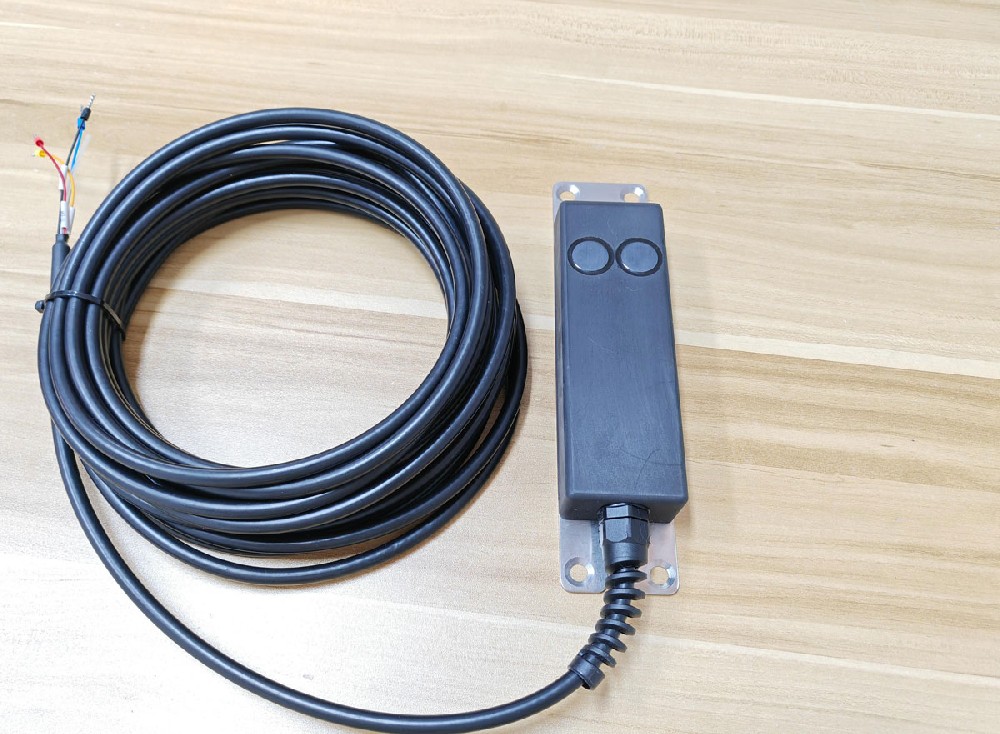
The following comparison uses the NiuBoL submerged Doppler velocity meter and non-contact radar flowmeter configurations. Velocity and distance performance are component specifications; they are not an overall percentage accuracy for calculated canal discharge. Section survey, velocity distribution and installation add their own uncertainty.
| Item | Submerged Doppler configuration | Non-contact radar flowmeter |
|---|---|---|
| Velocity range | 0.03-5 m/s for the unidirectional version | 0.1-20 m/s |
| Level measurement | Pressure-derived depth; 0.03-5 m configuration | Radar distance, 0.1-65 m; full flow operation has a separate installation-height limit |
| Radar component performance | Not applicable | Listed velocity accuracy +/-2%; distance accuracy +/-1 mm |
| Radar installation height | Not applicable | 0-20 m operating-height specification; determine the actual mount from the site |
| Radar supply and consumption | Select supply and load from the delivered Doppler version | 10-30 VDC; maximum 1.3 W |
| Radar operating environment | Use the submerged unit's specified service limits | -40 to 80 C; 0-95% RH, non-condensing |
| Data interface | RS485 Modbus RTU | RS485 Modbus RTU |
| Immersion protection | IP68 for the submerged probe | Above-water installation; do not apply the Doppler probe's rating to the radar assembly |
Specify cable length, jacket material, connectors and supply demand for the actual delivered version. The Doppler instrument's vented pressure-reference path must remain open to atmosphere and protected from moisture. For radar, distinguish its long level-ranging capability from the shorter height at which the complete velocity-and-level arrangement is intended to operate.
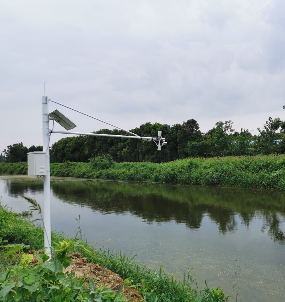
The field sensor supplies local measurements over RS485 Modbus RTU. An RTU or data logger polls those measurements, stores records and provides the selected onward connection. Cellular, Ethernet or fiber-based networking requires suitable equipment and configuration. Modbus support at the sensor does not by itself establish compatibility with a district management platform.
Agree a record containing station identity, measurement time, level, velocity, discharge, cumulative volume and available quality or device-status information. Define units and decimal scaling before import. Where direction is supported, ensure negative values are decoded correctly rather than becoming large positive numbers.
For sites with intermittent coverage, choose local retention and a tested upload-recovery procedure. Delayed records must retain the time of measurement, and duplicate transmissions must not be counted twice. If the instrument does not expose a quality indicator, the acquisition system should at least distinguish a fresh response from a timeout or stale value.
Size solar supply using the selected sensor, RTU, modem and any auxiliary equipment, including transmission peaks and the difficult seasonal charging period. A low sensor load alone does not establish continuous station operation. Provide a recovery plan for low battery, network interruption and seasonal shutdown instead of relying on an uninterrupted-operation promise.
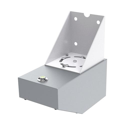
Acceptance should compare the installed system with an appropriate independent reference over several representative depths and flows. Include the normal gate configurations and any expected backwater conditions. Use synchronized observations and record the section geometry, instrument position and correction settings used during each comparison.
A single agreement at mid-flow cannot validate the low-flow limit, reverse-flow behavior or a changed section after sediment deposition. If disagreement grows with depth or gate position, investigate the velocity relationship and hydraulics rather than adjusting one coefficient until the average error appears small. Agree the required limits with the project before collecting acceptance data.
Also test the information chain: interrupt communications, perform an authorized controlled restart and export the resulting records. Confirm that cumulative totals remain interpretable and missing periods are identified. A fixed trial duration alone is not proof of correct water measurement if it never includes the operating conditions that challenge the station.
For a NiuBoL proposal, provide the canal cross section, minimum and maximum depths, expected velocity and direction, gate locations, sediment conditions, mounting access, power and network availability. Include the reference method and intended use of the totals. These inputs determine whether a submerged, above-water or alternative measuring arrangement is appropriate.

Sometimes. A velocity-area method may use the existing canal, but only when the section, flow conditions and installation support a representative measurement. It still needs mounting work, a survey and field verification. An unsuitable reach may require relocation or another method.
No. It avoids direct burial of the overhead sensor, but sediment changes the wetted section and can alter the velocity distribution. Update the geometry and check the flow relationship after significant deposition or dredging.
No. The usable measurement also depends on submergence or radar return, section geometry and the quality of the signal. Check the intended installation at its low-flow condition. A range specification alone cannot establish that the channel is measurable.
Do not assume so. The cited 0.03-5 m/s Doppler configuration is unidirectional. Where reverse flow can occur, specify the required bidirectional behavior and test sign, counter and net-volume handling on the selected unit.
No. Calculated volume includes velocity conversion, channel area, time integration and data continuity. Settlement use also depends on the project's accepted measurement and verification requirements. Evaluate the complete installed system rather than one component specification.
Inspect mounting stability, cables, deposits, debris and the measurement section. Submerged equipment may need cleaning and pressure-inlet checks; overhead equipment needs bracket and antenna inspection. Recheck after floods, channel works or significant sediment movement.
Often it can, provided the chosen RTU can deliver the required data format, timestamps and units to that platform. Request a sample record and test ingestion before rolling out many sites. Sensor-side Modbus compatibility is only one part of the connection.
Irrigation district flow monitoring begins with the canal and ends with a defensible water total. Choose the sensor around the hydraulic conditions, survey the section, validate velocity conversion and test recovery from interrupted data. That provides a sound basis for operational allocation and project acceptance without assuming every canal suits the same equipment.
Prev:Irrigation Canal Water Balance: Investigate Apparent Conveyance Loss
Next:Irregular Channel Flow Measurement: Build a Valid Stage-Area Table
Related recommendations
Sensors & Weather Stations Catalog
 Agriculture Sensors and Weather Stations Catalog-NiuBoL.pdf
Weather Stations Catalog-NiuBoL.pdf
Agriculture Sensors Catalog-NiuBoL.pdf
Water Quality Sensor Catalog-NiuBoL.pdf
Related products
 Combined air temperature and relative humidity sensor
 TDR Soil Moisture & Temperature Sensor for irrigation| RS485 |4-20mA| NBL-S-THR
 Soil pH sensor RS485 soil Testing instrument soil ph meter for agriculture |NBL-S-PH
 Wind Speed sensor Output Modbus/RS485/Analog/0-5V/4-20mA
 Tipping bucket rain gauge for weather monitoring auto rainfall sensor RS485/Outdoor/stainless steel
 Pyranometer Solar Radiation Sensor 4-20mA/RS485


Screenshot, WhatsApp to identify the QR code
WhatsApp number:+8615367865107
(Click on WhatsApp to copy and add friends)

