





— Blogs —
—Products—
 Consumer hotline +8618073152920
WhatsApp:+8615367865107
Address:Room 102, District D, Houhu Industrial Park, Yuelu District, Changsha City, Hunan Province, China
Product knowledge
Time:2024-09-24 16:04:36 Popularity:3468
Weather station surge protection must match the circuits that connect the instruments, logger, power source and receiving equipment. A protector for an AC supply is not automatically suitable for a 12 V sensor or an RS485 data pair. Identify each interface and its operating requirements, then have a qualified protection specialist select and coordinate the protective arrangement. A mast rod alone does not protect every electrical path.

A modular weather station can have several exposed connections: sensor power, RS485 buses, analog channels, rain-gauge contacts, a solar charging circuit and a copper link to another building. Damage can occur through these connections without a direct strike on the sensor head. The protection review therefore needs more than the mast height.
Prepare a circuit schedule showing each device, interface, supply and cable route. Mark the enclosure entries and connections to other structures. Keep the lightning-protection, electrical and instrumentation designers involved: a change intended to protect one circuit must not create an unsuitable signal path or compromise the agreed bonding arrangement.
| Connection | Information needed for selection | Why a generic protector is insufficient |
|---|---|---|
| AC supply feeding station equipment | Supply system, protective arrangement and downstream equipment. | Its voltage and coordination requirements differ from the low-voltage sensor circuits. |
| DC instrument supply | Normal voltage range, load current, wiring and equipment withstand information. | A device chosen only from the nominal voltage may not suit the actual supply or load. |
| RS485 data pair | Interface limits, data rate, reference arrangement and protection-device electrical characteristics. | Extra loading or an unsuitable voltage level can disrupt communication. |
| 4-20 mA or voltage signal | Signal type, loop supply, receiving input and permitted circuit loading. | The receiving circuit may lose measurement range or fail if the added device is incompatible. |
| Rain-gauge contact or pulse circuit | Contact type, excitation, input threshold and counting behavior. | A data-line or power protector cannot be assumed suitable for that input. |
The schedule should describe the delivered configuration, not every option in a product family. For the wider mast and earthing assessment, see small weather station lightning protection. The circuit checks here complement that assessment rather than replace it.
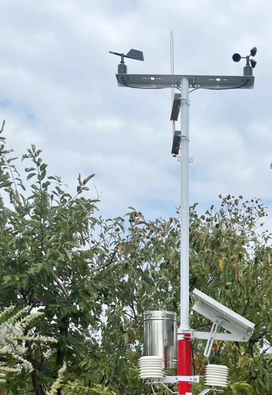
The NBL-W-LBTH uses DC 12-24 V and is available with RS485 Modbus RTU or selected analog output. The NBL-W-SS has several output options, including pulse, analog and RS485. Their similar position on a weather mast does not make their circuits interchangeable.
| Example component | Relevant specification | Protection-design input |
|---|---|---|
| NBL-W-LBTH | DC 12-24 V; selected RS485 Modbus RTU or 4-20 mA version. | Identify both the supply circuit and the delivered measurement interface. |
| NBL-W-SS / NBL-W-DS | Supply and output depend on configuration; IP65. | Check the exact wiring and interface. IP65 is not a lightning-withstand specification. |
| NBL-W-RS | Selected contact, voltage or RS485 output; supply depends on version. | Distinguish a counting input from an active digital or analog circuit. |
| TG462/TG462S | DC 5-35 V input; three RS485 ports; two Ethernet interfaces; IP30. | Review connected ports and the protective enclosure, not only the main power input. |
A logger's wide input range does not establish the permitted voltage for every connected sensor. Likewise, connecting an RS485 instrument does not mean all other devices on the mast use Modbus RTU. Ask NiuBoL for the actual equipment and interface schedule needed by the protection designer.
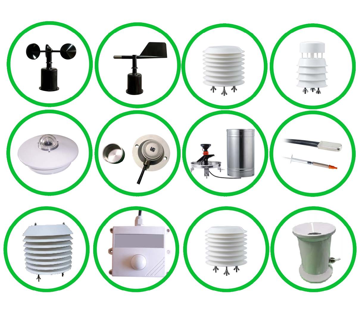
The selected device must support the electrical behavior of the installed interface while limiting the surge seen by the protected equipment. Its continuous operating voltage, protective characteristics and loading need review against the circuit. Do not select solely from an advertisement saying that a device is suitable for communications.
Have the designer address the reference conductor, shielding, isolation and bonding as a coordinated arrangement. Do not improvise a universal rule to connect every shield at both ends or leave every shield disconnected. Cable routing and the physical placement of protective devices also belong in the approved installation drawing.
After installation, test communication using the actual devices and settings. Check individual addresses, data freshness and plausible decoded values. A station that communicates before the protection devices are fitted still needs a final functional check with the completed circuit.
An air-termination system, current path and earth termination address a different part of the installation from a signal-line protector. Neither should be treated as a substitute for the other. The IEC 62305-4:2024 overview covers surge-protection measures for electrical and electronic systems within structures. Its applicability and the required local standards must be assessed for the actual project.
No standard mast photograph supplies the necessary construction design. Rod position, separation, conductor routing, electrodes and testing depend on the site. Do not copy a fixed pole height, offset or buried-grid dimension into a new project without a competent design review. Protection reduces risk; it does not guarantee that every lightning event leaves the station operating.
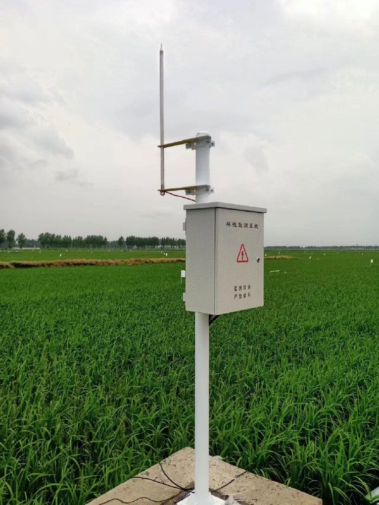
A logger inside a building can remain connected to outdoor sensors through copper cables. The National Weather Service indoor lightning guidance explains that lightning can enter structures through external conductors and affect connected systems. An indoor cabinet location therefore does not justify omitting the assessment.
A cellular or optical communications path may remove a particular conductive data connection, but power cables, sensor wiring, supports and other connections remain. Solar power is not proof of lightning immunity. Review the complete arrangement rather than replacing one copper link and declaring the station protected.
Do not approach a mast or handle cables during a thunderstorm, and do not attempt to disconnect exposed equipment as a storm-time protective action. Apply the site's safe-access and electrical-isolation procedures; a weather station's rain or wind reading is not a lightning all-clear signal.
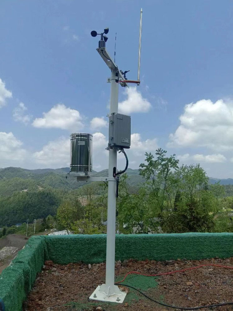
The responsible specialist should inspect and test the protective installation against its design. Separately, the instrumentation team should verify supply conditions, communication, analog values and rain counts. A normal dashboard does not establish that a surge protector or earth connection remains effective.
Record protective-device identifiers and any status indications with the circuit drawing. After a suspected event, damaged wiring or changed protection indication requires qualified assessment before equipment is returned to service. Keep unavailable channels visibly unavailable rather than interpreting them as calm wind or no rain.
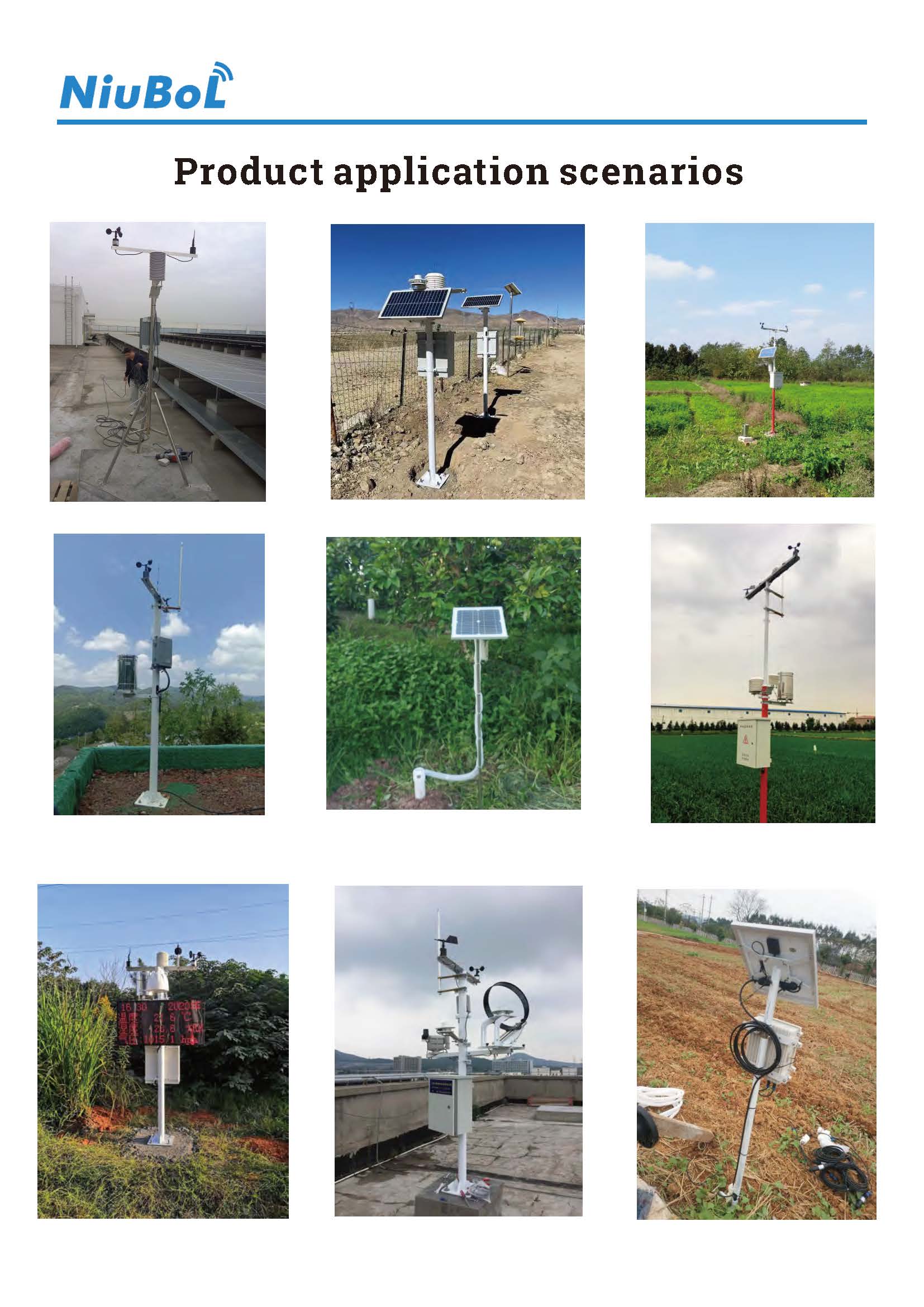
No. It does not automatically protect separate DC supplies, signal pairs or external communication paths. The protection design must identify the circuits and coordinate suitable measures for their actual electrical requirements.
No. IP65 describes ingress protection, not surge withstand or a lightning-protection system. The NBL-W-SS and NBL-W-DS are rated IP65, but their supply and output circuits still require separate assessment.
No. Confirm compatibility with the interface, operating voltage, data rate and circuit loading. Include the device in the completed communications test rather than assuming that an unchanged wiring label proves compatibility.
No. Outdoor sensor, power or communication cables may still provide connected paths. Review the entire installation and the building interface, not just the location of the logger enclosure.
Do not handle exposed equipment or cables during a thunderstorm. Follow the site's safety procedures. Equipment protection should be designed and installed in advance, not improvised through storm-time work.
Provide the equipment list, selected interfaces and supplies, cable routes, mast and cabinet layout, and connections to buildings. Have the qualified protection designer specify the protective devices and installation requirements; do not request a universal grounding kit without those inputs.
Weather station surge protection is a circuit-specific design task. Identify the actual power and signal paths, coordinate protection with the site design, and verify instrument operation after installation. NiuBoL equipment details can support that work, but no rod, ingress rating or generic protector establishes complete lightning immunity.
Related recommendations
Sensors & Weather Stations Catalog
 Agriculture Sensors and Weather Stations Catalog-NiuBoL.pdf
Weather Stations Catalog-NiuBoL.pdf
Agriculture Sensors Catalog-NiuBoL.pdf
Water Quality Sensor Catalog-NiuBoL.pdf
Related products
 Combined air temperature and relative humidity sensor
 TDR Soil Moisture & Temperature Sensor for irrigation| RS485 |4-20mA| NBL-S-THR
 Soil pH sensor RS485 soil Testing instrument soil ph meter for agriculture |NBL-S-PH
 Wind Speed sensor Output Modbus/RS485/Analog/0-5V/4-20mA
 Tipping bucket rain gauge for weather monitoring auto rainfall sensor RS485/Outdoor/stainless steel
 Pyranometer Solar Radiation Sensor 4-20mA/RS485


Screenshot, WhatsApp to identify the QR code
WhatsApp number:+8615367865107
(Click on WhatsApp to copy and add friends)

