





— Blogs —
—Products—
 Consumer hotline +8618073152920
WhatsApp:+8615367865107
Address:Room 102, District D, Houhu Industrial Park, Yuelu District, Changsha City, Hunan Province, China
Product knowledge
Time:2025-03-25 09:12:15 Popularity:1578
Small weather station lightning protection requires a site-specific assessment of the mast, earthing, bonding and every connected cable. A rod or a low earth-resistance reading alone does not establish protection. Surge protection must suit the actual power and signal circuits, and no station configuration can guarantee survival of every lightning event.

A station can suffer damage without a direct strike to the instrument mast. Nearby lightning can induce surges in field wiring, and a surge can arrive through an external power or communication connection. Conversely, installing a metal mast does not justify saying that the station simply attracts lightning. The relevant question is the exposure of the whole installation and the consequences of a fault.
Start by identifying people who may access the site, the mast and foundation arrangement, cable routes, the cabinet and connections to other buildings or equipment. A solar-powered station with cellular communication has a different connection layout from a station linked to a building through long copper cables. Neither is automatically safe merely because it is small.
The IEC 62305-1:2024 overview describes general lightning-protection principles for structures and their installations. The IEC 62305-2:2024 overview addresses risk management. A qualified designer must determine their applicability, the local rules and the measures appropriate to the project; these public summaries do not provide a complete construction design.

An air-termination arrangement must be designed together with its current path, earth termination and the necessary bonding or separation. Adding a rod above a weather head does not establish its protection zone or confirm that current will avoid sensor wiring. Its position may also affect wind exposure, shade a radiation sensor or obstruct a rain collector, so protection and measurement layout need to be reviewed together.
Do not use a standard weather-station photograph as a construction drawing. The correct arrangement depends on geometry, materials, structural loads and electrical connections that may not be visible. In particular, a loose conductor or disconnected earth electrode cannot be judged from the appearance of the mast top. An installation contractor should work from the approved design rather than improvise a grounding path through sensor brackets.
An earth-resistance test is useful only with an identified method, test conditions and applicable acceptance criterion. A value below 4 ohms is not a universal declaration that any station is protected. Lightning involves fast transient currents; conductor routing, connections, bonding, electrode arrangement and separation still matter. The project designer should specify the required tests and limits.
Keep test records with the electrode arrangement and inspection location so that future measurements can be interpreted. Soil moisture and seasonal conditions can affect results. A changed reading should be investigated against comparable test conditions and the physical condition of connections, rather than dismissed because the station is still transmitting data.

| Circuit or interface | Information needed for SPD selection | Practical compatibility check |
|---|---|---|
| DC sensor or logger supply | Nominal and maximum operating voltage, polarity, load and earthing arrangement | The device must tolerate normal operation and coordinate with the protected equipment and upstream protection. |
| RS485 Modbus RTU | Interface voltage limits, conductor count, signal reference and communication speed | Check communication with the selected protector installed; Modbus compatibility is not surge immunity. |
| 4-20 mA or voltage output | Loop power arrangement, compliance voltage or input range | Check added voltage drop, leakage and measurement loading rather than choosing only by connector size. |
| Pulse rain input | Contact or driven-output type, input thresholds and cable route | Confirm valid pulse counting and absence of false counts after protection is fitted. |
| External copper communication | Interface type and connections between earthing environments | Review entry points and both connected ends; one cabinet device may leave another route unprotected. |
The IEC 62305-4:2024 overview covers surge-protection measures for electrical and electronic systems within structures. Selectors must consider the complete protective arrangement, not just the presence of an SPD label. This overview is not evidence that a particular NiuBoL station or accessory has been assessed to that standard.
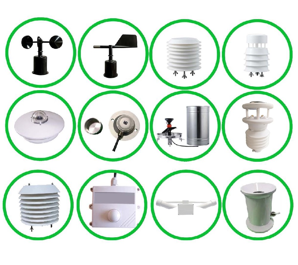
NiuBoL modular stations can use separate wind, air and rain instruments. That gives the integrator several circuits to inspect, not one generic protected connection. The NBL-W-LBTH has RS485 Modbus RTU and 4-20 mA versions; the ordered output determines the circuit design. Wind sensor interfaces must likewise be identified from the actual configuration rather than assumed from the housing.
| Station item | Parameter relevant to installation | What it does not establish |
|---|---|---|
| NBL-W-SS and NBL-W-DS wind sensors | IP65 | IP65 is not a lightning-withstand or surge-immunity rating. |
| NBL-W-LBTH air sensor | 12-24 V DC; interface selected as RS485 Modbus RTU or 4-20 mA | A matching nominal supply does not by itself establish SPD coordination. |
| TG462/TG462S logger family | 5-35 V DC supply; IP30 | The logger needs suitable enclosure protection outdoors; the enclosure does not supply lightning protection. |
Shielded cable helps manage interference only as part of an appropriate installation. It is not a substitute for bonding, earthing or surge protection, and there is no single shield-termination instruction suitable for every circuit arrangement. Follow the project design and equipment requirements. Mark the termination arrangement so a replacement technician does not change it unintentionally.

Do not visit or work on the mast during an approaching or active thunderstorm. Follow the site's electrical isolation and access procedures when conditions are safe. Check visible damage, loose bonding connections, affected cable entries and SPD status indicators. An indicator shows the condition described by its manufacturer; it is not a complete test of the installation.
Before accepting resumed data, compare local sensor output with the logger and remote record. Surges may damage one channel while others remain online. Check rainfall for false counts, wind direction for a fixed value and timestamps for logger resets. Preserve affected intervals with fault flags; a plausible numerical output is not proof that the instrument remains within its measurement accuracy.
Set inspection frequency from the design, environmental deterioration, incident history and local obligations. Record replacements by circuit and model. Repeated failures deserve a review of the protection arrangement and cable routes rather than an automatic purchase of another identical sensor.
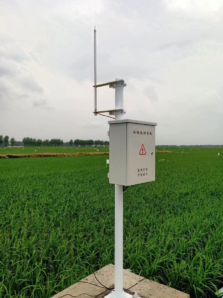
Yes. Solar power removes one possible external supply route but leaves the mast, photovoltaic wiring, sensor cables and electronic equipment exposed. The actual layout determines the appropriate measures.
Not without demonstrating compatibility with every protected circuit. RS485, analog loops, pulse inputs and DC power have different operating limits. Identify each circuit and select a coordinated arrangement.
No. Use the criterion and method required by the approved design and local rules. Also inspect the physical current path, connections, bonding, separation and protection of incoming circuits.
A standard weather station measuring wind, air and rain is not a lightning-detection system. A warning function requires separately specified equipment or a service and an operational response procedure.
Provide site and mast drawings, power details, sensor interfaces, cable lengths and routes, and connections to other equipment. Ask who supplies the design, installs the protection, performs tests and maintains it. A rod-only price cannot be compared with that complete scope.
No. Protection reduces risk but cannot eliminate every event or failure. Critical monitoring may also need spares, a recovery plan and clearly flagged data gaps; backup equipment does not make unsafe site access acceptable.
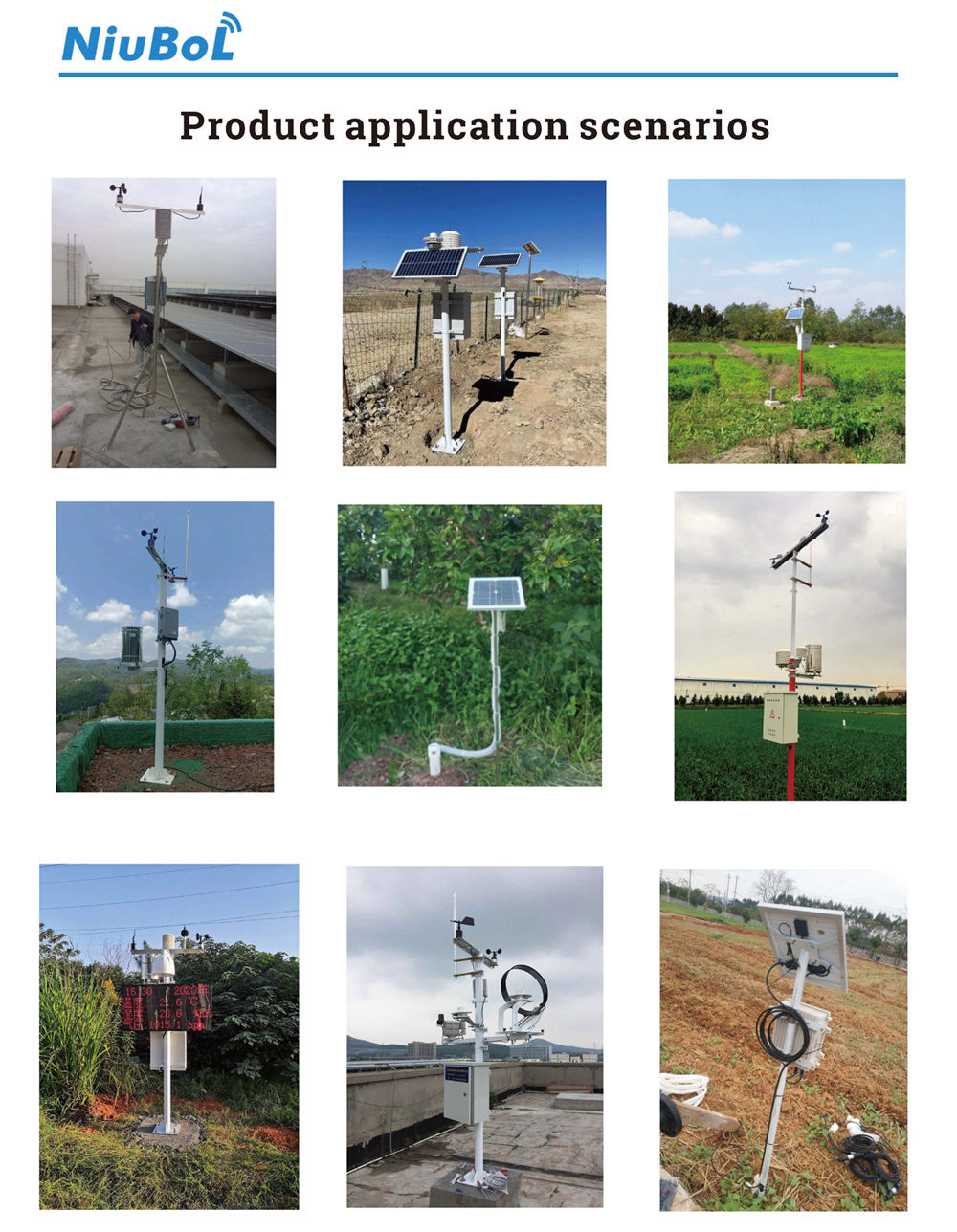
Small weather station lightning protection should be designed around the site and connected circuits. Request interface details from NiuBoL, and have the responsible protection specialist assess the mast, earthing, bonding and surge devices together. Accept the installation against its design and test records, not against a photograph, a single resistance number or an assurance of complete immunity.
Prev:Solar Radiation Monitoring Station: Define Each Measurement Channel
Next:Small Weather Stations for Agriculture: Which Field Decisions Can They Support?
Related recommendations
Sensors & Weather Stations Catalog
 Agriculture Sensors and Weather Stations Catalog-NiuBoL.pdf
Weather Stations Catalog-NiuBoL.pdf
Agriculture Sensors Catalog-NiuBoL.pdf
Water Quality Sensor Catalog-NiuBoL.pdf
Related products
 Combined air temperature and relative humidity sensor
 TDR Soil Moisture & Temperature Sensor for irrigation| RS485 |4-20mA| NBL-S-THR
 Soil pH sensor RS485 soil Testing instrument soil ph meter for agriculture |NBL-S-PH
 Wind Speed sensor Output Modbus/RS485/Analog/0-5V/4-20mA
 Tipping bucket rain gauge for weather monitoring auto rainfall sensor RS485/Outdoor/stainless steel
 Pyranometer Solar Radiation Sensor 4-20mA/RS485


Screenshot, WhatsApp to identify the QR code
WhatsApp number:+8615367865107
(Click on WhatsApp to copy and add friends)

