

— Blogs —
—Products—
 Consumer hotline +8618073152920
WhatsApp:+8615367865107
Address:Room 102, District D, Houhu Industrial Park, Yuelu District, Changsha City, Hunan Province, China
Product knowledge
Time:2022-05-10 21:11:35 Popularity:2092
Quick answer: Select soil sensor output signals by matching the receiving equipment, cable distance, electrical noise and number of measurement points. RS485 is suited to multi-sensor digital networks, 4-20 mA is familiar in PLC and industrial analog systems, and voltage output is usually reserved for short, controlled wiring runs. The ordered sensor must actually support the selected interface; it cannot be inferred from the probe's appearance.
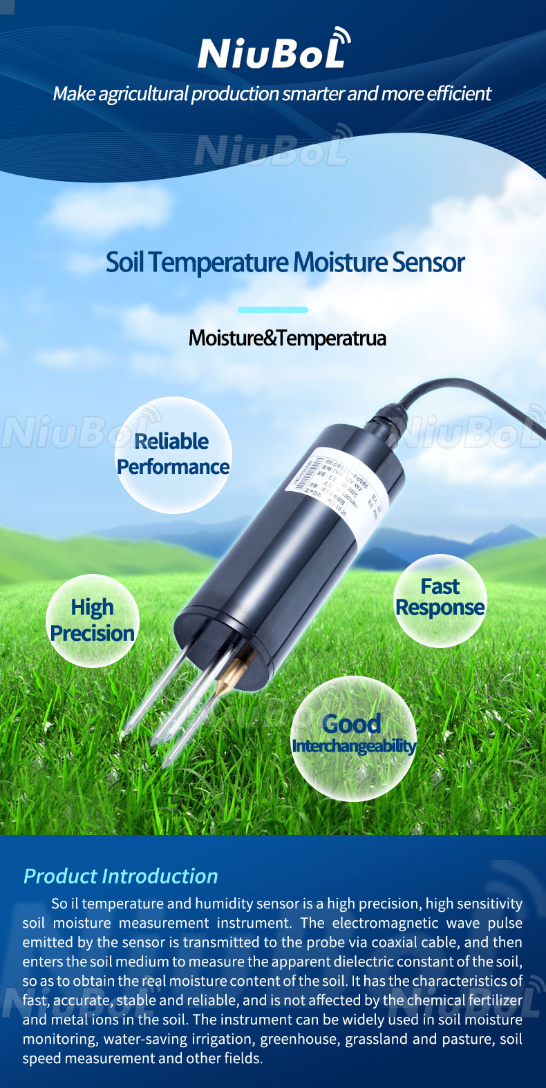
Soil temperature, volumetric water content and electrical conductivity are different measurements. The output interface does not determine what the probe measures. Procurement documents should therefore list the parameter, required range and accuracy separately from the signal type.
This distinction matters because a page or quotation may use the general term “soil sensor” while the control system expects one specific variable. A temperature-only probe, a temperature-and-moisture probe and a three-parameter temperature/moisture/EC probe may use the same RS485 wiring but expose different registers.
| Output | Suitable use | Integration checks |
|---|---|---|
| RS485, commonly with Modbus RTU | Multiple field sensors, data loggers, RTUs and PLC networks | Confirm baud rate, parity, device address, register map, byte order and grounding. |
| 4-20 mA | Industrial analog input cards and long cable runs where a current loop is preferred | Confirm active or passive loop arrangement, supply voltage, load resistance and scaling. |
| 0-5 V or 0-10 V | Short runs to a compatible analog input in a controlled electrical environment | Confirm common ground, input impedance, cable voltage drop and signal scaling. |
| SDI-12 or other digital interface | Specialized environmental data loggers where the exact sensor version supports it | Confirm protocol version, command set, addressing and logger compatibility. |
RS485 defines differential signaling; it does not by itself define register addresses or data meaning. Many industrial soil sensors carry Modbus RTU over RS485, but the PLC or logger still needs the supplier’s register map. Do not assume that two sensors with the same connector use the same register order.
A typical two-wire half-duplex bus uses a daisy-chain layout. Avoid star branches, assign a unique address to every device, and terminate only where required by the cable length and network design. Keep the communication pair away from motor and inverter cables, and follow the controller manufacturer’s grounding guidance.
A NiuBoL NBL-S-TM provides a concrete example: it reports soil temperature and volumetric moisture using RS485 Modbus RTU. A NBL-S-TMC adds conductivity. Those digital configurations do not acquire a 4-20 mA or voltage output simply because the controller has an analog input. Select an actual analog variant or an appropriate separate conversion device when the project requires one.
| NBL-S-TM digital configuration | Specification |
|---|---|
| Soil temperature | -40 to 80 C; 0.1 C resolution; +/-0.5 C accuracy |
| Volumetric soil moisture | 0-100%; 0.1% resolution; +/-5% accuracy specification; agree the error basis for the acceptance conditions |
| Supply | 5-24 VDC or 12-24 VDC, according to the selected configuration |
| Output | RS485 Modbus RTU |
| Example digital wiring | Red supply positive; black negative; yellow RS485 positive; blue RS485 negative |
| Probe and operating environment | IP68; -40 to 85 C environment; temperature measurement range remains -40 to 80 C |
| Cable and sealing | Standard 5 m cable, jacket material to suit exposure; epoxy-sealed probe with alloy electrodes |
| Load and timing | Confirm current demand and startup time for the selected version; serial reads must respect the device response interval |
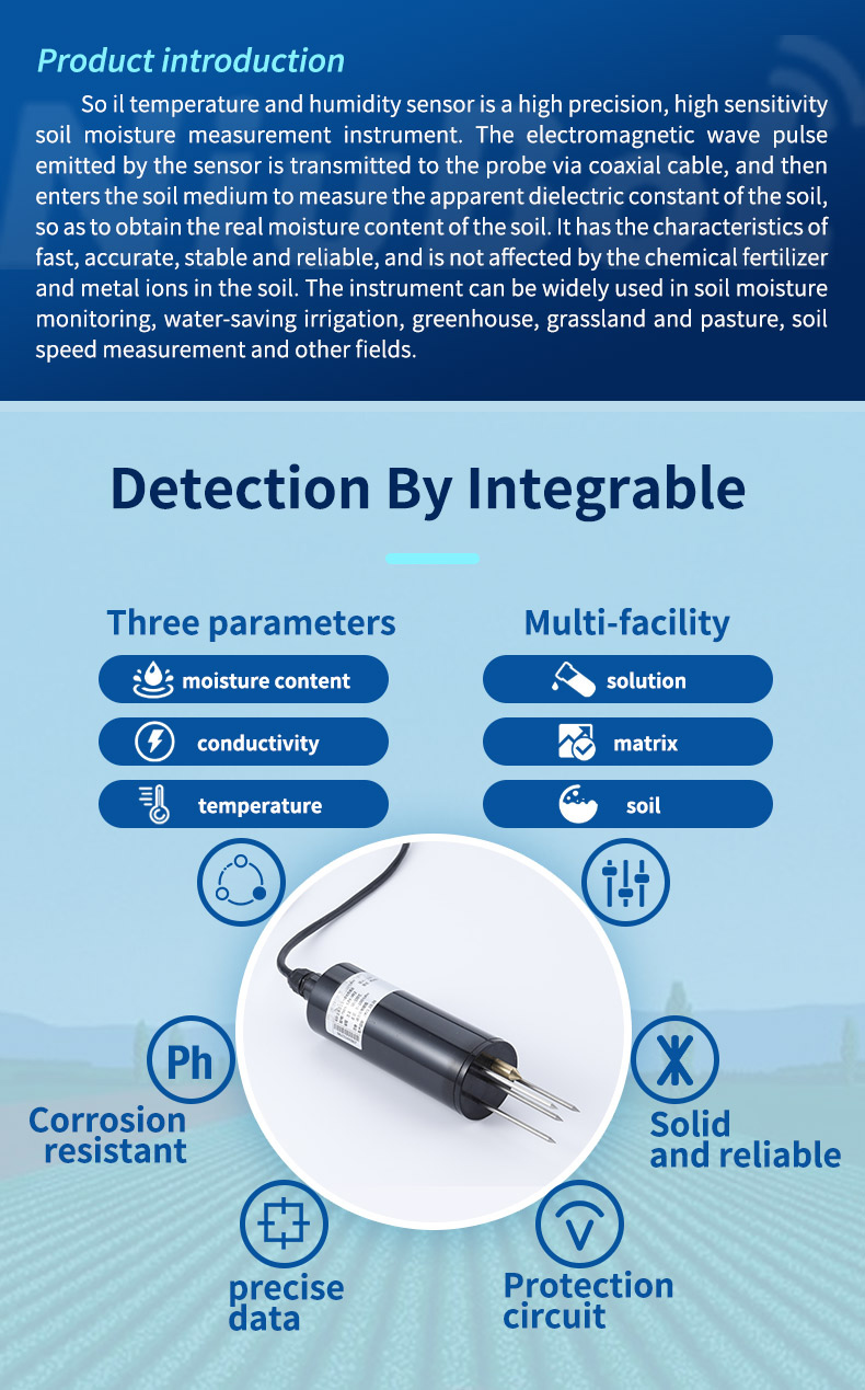
Use the ordered unit's wiring for termination work. An integrated probe can contain several measurements without separate analog output wires for each one. The product illustrations show sensing options, not a universal connector or wiring diagram for every soil sensor.
Start with one device, a correctly rated supply and a known working serial interface. Read the required channels, confirm their units and test a plausible temperature/moisture condition. Assign unique addresses before combining devices. Address and communication settings may differ between models even within one project.
A temperature value needs its correct sign and scale. For an illustrative encoding example, a signed 16-bit integer of -125 with a scale of 0.1 represents -12.5 C. Interpreting the same bit pattern as unsigned gives 65411, an obvious integration error. This example is not a claim that every NiuBoL sensor uses that encoding; verify the selected register definition.
Check polling limits and timeout behavior at the planned network size. If eight devices each need a one-second service slot, a sequential cycle takes at least eight seconds before extra delays and retries; that is a scheduling example, not a sensor performance rating. Adding devices can change update age even when every transaction succeeds.
A serial bus needs an appropriate trunk, end termination and common reference arrangement. Select cable, termination, bias and grounding together. Do not promise a fixed communication distance solely from the RS485 label, and do not add a terminating resistor at every probe.
Identify whether the transmitter is loop-powered or separately powered and whether the receiving input supplies loop power. A two-wire passive transmitter and an active current output are not connected by the same universal diagram. Incorrectly joining two powered devices or leaving a passive loop unpowered can prevent measurement and may damage equipment.
For a verified linear current-output transmitter, PLC analog input scaling is X = L + (I - 4) x (U - L) / 16, where I is in mA and L/U are the assigned engineering limits. If a hypothetical temperature transmitter maps -20 to 80 C, 12 mA means 30 C. These are assumed endpoints, not an NBL-S-TM analog specification.
The loop also needs sufficient voltage. With an assumed 24 V supply, a transmitter requiring at least 12 V and no other drops, the theoretical resistance budget at 20 mA is (24 - 12) / 0.020 = 600 ohms. Cable, input resistance and other series devices consume that budget; allow the required design margin. Do not apply this example to a transmitter with different voltage requirements.
Use a suitable current source to check the input at 4, 12 and 20 mA with the process disconnected or made safe. Then test the actual sensor through the installed loop. Treat open-circuit and out-of-range values according to the supported device behavior; no universal fault current should be assumed.
Verify both signal range and receiver input limits. A 0-10 V output is not suitable for a 0-5 V input merely because the same terminals are labelled analog. Some inputs can be damaged by an excessive signal; software scaling does not protect the hardware.
For a hypothetical 0-5 V signal representing 0-100% VWC, the scaling is 20 percentage points per volt. A 0.1 V error caused by reference offset would therefore be 2 percentage points of VWC. That is an electrical error example, not the soil measurement accuracy. Compare the voltage at the sensor reference and the controller input before changing a soil calibration.
Receiver impedance and cable resistance matter. Route signal and return deliberately, separate them from switching loads and follow the equipment's shielding and bonding requirements. A higher-resolution analog converter cannot remove a ground offset already present at its input. Where the installation cannot control those conditions, consider a compatible current or digital arrangement.
Use RS485 when one logger must poll several sensors or when digital values should remain unchanged by analog scaling. Use 4-20 mA when the plant standard is analog instrumentation, the PLC has spare current inputs and each variable can be allocated a channel. A voltage output can be economical for a nearby controller, but it is more sensitive to ground offset and voltage drop.
For remote agricultural stations, also consider power consumption and wake-up behavior. The data logger must allow enough stabilization time before polling a switched sensor supply. If the sensor remains powered continuously, include that load in the solar-panel and battery calculation.
Separate agricultural data logger integration into a receiver test and a sensor test. First establish the port, signal range and scaling with suitable test equipment. Then install the probe with proper soil contact and verify an actual response. Passing an electrical input test does not establish moisture accuracy in a particular soil.
Check a disconnected cable, loss of power and recovery after a controller restart. Record what the application displays during failure: unavailable, stale or an identified fault. A communication timeout is not zero moisture. For irrigation, stop the acceptance test from inadvertently operating valves or pumps.
NiuBoL soil sensing options can be reviewed in the agricultural sensor category. For a quotation, provide the measured parameters, output, power supply, cable length, installation depth, soil conditions and receiving device.
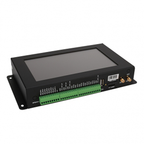
Not without an interface. Use a serial device server, IoT gateway or data logger that reads the RS485 protocol and forwards data through Ethernet or another upstream network.
Not automatically. Measurement accuracy comes from the sensing element and calibration. The interface affects transmission and integration error, so the complete loop must be evaluated.
Yes, when an integrated digital sensor is designed to report both values. For analog versions, each output may require a separate input channel; confirm the wiring diagram.
It can when it correctly polls the protocol and maps the required channel to a supported analog output. Include its supply, scaling, update time and fault behavior. A passive cable adapter cannot perform that conversion.
Compare the measured quantity, supply, connector, pin assignment and receiver configuration. For digital units, check registers and signed values; for analog units, check the engineering endpoints and loop arrangement. Similar shape is not sufficient.
Only when the chosen sensor and acquisition timing support it. Allow verified startup and stabilization before reading. Include repeated startup demand and ensure power cycling does not erase required configuration.
Specify parameters, ranges, exact output, supply, receiver, cable length and environment. Include any converter, isolated interface or separate analog channels needed. An inexpensive probe may not reduce the installed cost when the receiving equipment must also change.
Choose the signal after defining the sensor parameter and control architecture. A clear interface specification prevents wiring changes, register conflicts and scaling errors during commissioning.
For NiuBoL selection, identify soil sensor output signals by the actual interface version and validate the complete path to the final engineering value. Keep the useful sensing decision separate from communication, wiring and receiver tests so an integration error is not mistaken for a soil condition.
Prev:Applications of soil temperature sensor
Next:Common Types of Soil Moisture Sensor Liquid Level Sensors
Related recommendations
Sensors & Weather Stations Catalog
 Agriculture Sensors and Weather Stations Catalog-NiuBoL.pdf
Weather Stations Catalog-NiuBoL.pdf
Agriculture Sensors Catalog-NiuBoL.pdf
Water Quality Sensor Catalog-NiuBoL.pdf
Related products
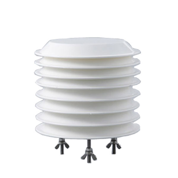 Combined air temperature and relative humidity sensor
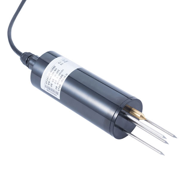 TDR Soil Moisture & Temperature Sensor for irrigation| RS485 |4-20mA| NBL-S-THR
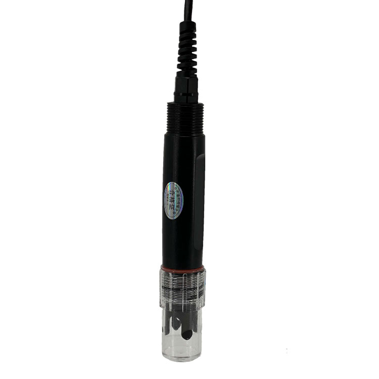 Soil pH sensor RS485 soil Testing instrument soil ph meter for agriculture |NBL-S-PH
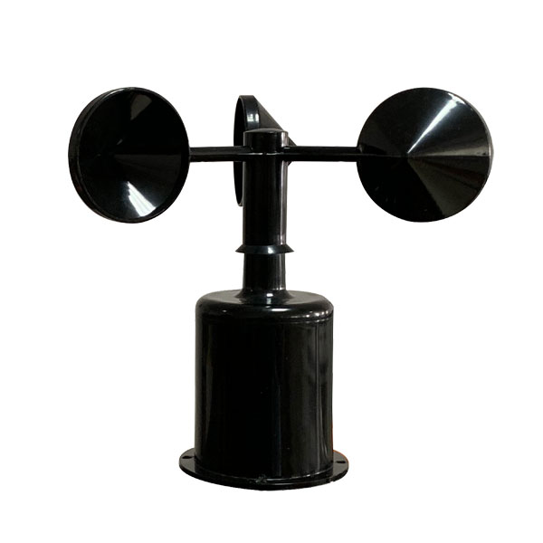 Wind Speed sensor Output Modbus/RS485/Analog/0-5V/4-20mA
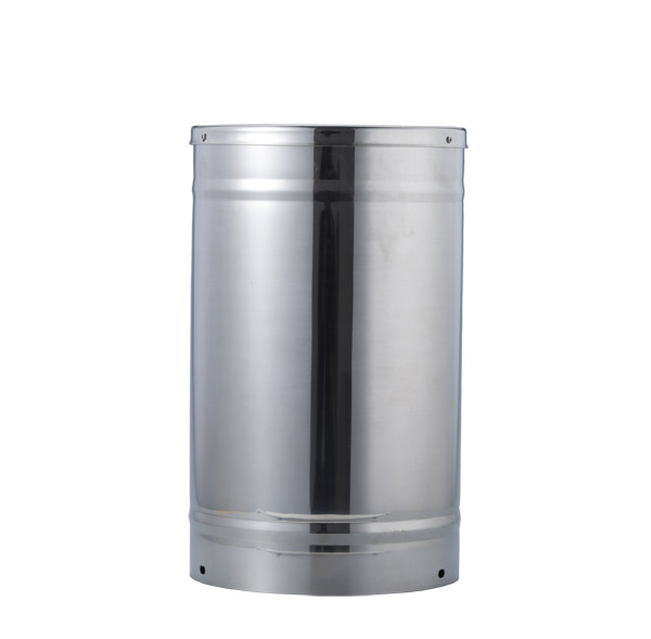 Tipping bucket rain gauge for weather monitoring auto rainfall sensor RS485/Outdoor/stainless steel
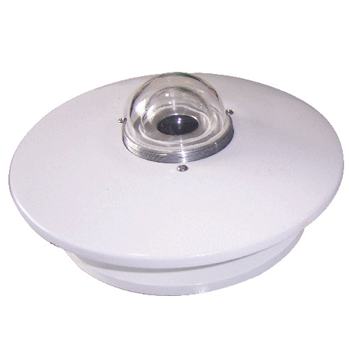 Pyranometer Solar Radiation Sensor 4-20mA/RS485

Screenshot, WhatsApp to identify the QR code
WhatsApp number:+8615367865107
(Click on WhatsApp to copy and add friends)