

— Blogs —
—Products—
 Consumer hotline +8618073152920
 WhatsApp:+8615367865107
Address:Room 102, District D, Houhu Industrial Park, Yuelu District, Changsha City, Hunan Province, China
Product knowledge
Time:2026-03-06 17:51:00 Popularity:545
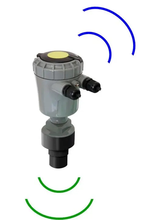
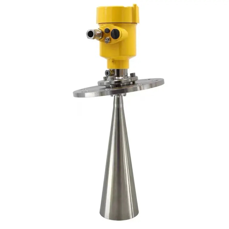
In the context of accelerating national flood control and drought relief command systems and hydrological modernization, real-time water level monitoring in small and medium rivers, reservoirs, power stations, and mountain flood channels has become a core component of hydrological automatic forecasting systems (HWSS). Traditional contact-type water level gauges (such as float-type and pressure-type) often face issues like sensor scaling, drift, mechanical wear, and high maintenance costs in high-sediment, easily silted, rapidly varying flow velocity, or complex bank slope sections. The NiuBoL radar water level gauge adopts 77–79 GHz FMCW millimeter-wave technology for non-contact measurement, with a blind zone ≤150 mm, full-range accuracy ±1 mm (typical conditions), power consumption only 0.6 W, IP67 protection, and is specifically designed for unattended field environments. It has been validated in high-sediment rivers, upstream reservoirs, tidal river sections, and urban inundation points.
This article focuses on engineering practice, providing a complete, directly implementable guide for system integrators, IoT solution providers, and project contractors—from site selection planning, installation specifications, operation and debugging, common fault troubleshooting, to long-term maintenance—to ensure long-term stable operation of the equipment under complex hydrological conditions.

The advantage of millimeter-wave radar water level gauges lies in extremely low attenuation from atmospheric parameters (temperature, pressure, humidity, rain, fog, snow) and immunity to water conductivity and suspended matter concentration. In high-sediment rivers, traditional ultrasonic or laser water level gauges are susceptible to sediment reflection interference or lens contamination, whereas the FMCW system combined with narrow beam (8°) design effectively suppresses false echoes from riverbanks, floating objects, drop structures, etc.
Typical application scenarios of radar water level gauges include:
Key sections of high-sediment rivers (e.g., Yellow River tributaries, southern mountain streams): Non-contact avoids sediment accumulation on sensors
Upstream and downstream of reservoir dams and reservoir areas: Long-range stable monitoring, supports reservoir capacity calculation
Mountain flood channels and urban drainage networks: Rapid response to flood peaks, optimized with fluctuation filtering algorithms
Tidal river sections and coastal sluices: Unaffected by salinity, accuracy not disturbed by tidal fluctuations
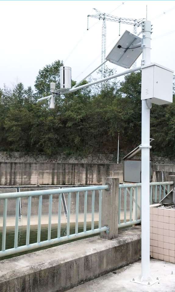
Remote unattended stations: Solar-powered + low power consumption, long continuous operation period
Actual engineering data shows that in river sections with sediment concentration >5 kg/m³, the annual maintenance frequency of millimeter-wave radar can be reduced to less than 1/5 of contact-type equipment.
| Parameter | Specification Value | Remarks and Engineering Significance |
|---|---|---|
| Operating Frequency Band | 77–79 GHz | FMCW, high resolution, narrow beam with strong anti-interference |
| Measurement Range | 0.15 m – 65 m | Covers from small channels to large reservoirs |
| Blind Zone | ≤ 0.15 m | Suitable for near-shore low water level monitoring |
| Resolution / Accuracy | 1 mm / ±1 mm (@4 m, 25℃, 40%RH) | Typical full-range ±2–3 mm |
| Beam Angle (3 dB) | 8° | Minimal interference, small safe installation distance from shore |
| Power Consumption | 0.6 W (average) | Solar system friendly, ≥7 days continuous in rainy conditions |
| Supply Voltage | DC 10–30 V | Recommended 12 V or 24 V to prevent voltage drop |
| Protection Rating | IP67 | Dustproof and waterproof, short-term submersion |
| Operating Temperature | -40 ℃ ~ +80 ℃ | Adaptable to extreme climates |
| Communication | RS485 (Modbus RTU, 9600,8N1) | Easy integration with RTU/gateway |
| Fluctuation Filtering | Supports multi-level algorithms | Handles rapid flows, drops, large waves |
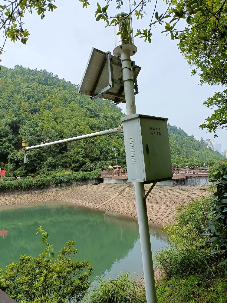
Elevation requirements: The installation reference plane must be 0.5–1.5 m above the local historical highest flood level (including super-standard flood margin), referring to local hydrological design specifications or flood control standards.
Common mistake: Position too low → Equipment washed away during flood peaks or long-term submersion leading to seal failure.
Recommendation: Overlay GIS flood inundation maps with historical extreme water level data during the design phase.
Site selection principles: Open water surface, no large drop structures/rapids; avoid inlets, outlets, mixing/vortex zones; stay away from strong electromagnetic sources (high-voltage lines, substations).
Horizontal distance to nearest bank wall/slope ≥ installation height × tan(4°) ≈ installation height × 0.07 (8° beam).
Verticality: Instrument axis must be strictly perpendicular to the average water surface, deviation ≤±1°.
Recommended tools: High-precision digital inclinometer + laser plumb bob. Tilt can cause >30% echo amplitude attenuation or even signal loss.
Fixing method: Stainless steel hydrological pole or dedicated bracket, at least three-point fixation, using anti-loosening nuts/locking washers. Wind resistance design verified against local maximum wind speed (≥35 m/s).
Beam clearance check: No objects (branches, buoys, bridge piers, guardrails, power lines) within the conical beam space (half-angle 4°) directly below the horn mouth.
Field method: Simulate beam path with laser pointer, or power on temporarily to view echo spectrum.
RS485 bus: Shielded twisted pair, A/B must not be reversed; add 120 Ω terminating resistor for bus >300 m.
Power supply: Independent circuit + three-level lightning protection (power/signal ports 20 kA); solar system battery capacity ≥5–7 times daily consumption.
Multiple devices in parallel: Each slave has a unique Modbus address (default 1).

Immediately after power-on, perform the following steps:
Zero point/installation height calibration: Input the actual distance from horn mouth to reference water surface to eliminate installation error.
False echo learning/suppression: Device supports automatic or manual learning of static interference (e.g., bank wall echoes), set suppression threshold.
Fluctuation filtering configuration: Adjust averaging count (5–60 times) and response time (1–30 s) according to river section characteristics, balancing accuracy and real-time performance.
Sampling interval: 1–5 min during flood season, 10–30 min during normal flow, balancing power consumption and data density.
Debugging tools: Dedicated host computer software or Modbus Poll, real-time viewing of echo curve, signal-to-noise ratio (SNR >20 dB is ideal).
In sections with high sediment content and abundant floating debris:
Increase installation height (reduce near-range floating object interference)
Enable enhanced filtering firmware (suppress transient echoes from sediment splashes)
Regular (quarterly) inspection and cleaning of horn mouth to avoid mud adhesion
Combine video surveillance or auxiliary ultrasonic for verification of extreme flood peak data
False jumps → Check for temporary objects in beam (floating debris, vessels, birds), or adjust filtering strength
Signal loss → Verify verticality, clean horn mouth, check supply voltage
Accuracy drift → Annual field comparison or sent for calibration (radiation sensors recommended traceable calibration every 2 years)
Maintenance cycle: Monthly visual inspection of horn mouth/bracket; quarterly dust/insect cleaning; annual full parameter verification
1. Will accuracy decrease during heavy rain or dense fog?
Millimeter waves have much lower attenuation in rain and fog than laser/ultrasonic; tested under 100 mm/h rainfall intensity, accuracy remains within ±3 mm.
2. How to calculate the minimum safe distance for shore installation?
Distance ≥ height × 0.07 (8° beam). For example, at 10 m height, bank wall distance ≥0.7 m.
3. How many devices can a multi-device RS485 bus support at most?
Theoretically 247 units, practically recommended ≤30 units to avoid signal attenuation.
4. What are the most common sources of false echoes and suppression methods?
Bank slopes, bridge piers, floating objects; suppress by software learning of static echoes.
5. Does it support remote parameter modification or firmware upgrade?
Current standard version requires on-site RS485 tools.
6. How to verify measurement accuracy after installation?
Compare with manual staff gauge or known reference points; check SNR and main echo integrity via echo curve.
The NiuBoL radar water level gauge, with high-frequency FMCW millimeter-wave as its core, combined with narrow beam, low blind zone, low power consumption, and powerful filtering algorithms, provides a highly reliable, non-contact solution for hydrological monitoring projects. The key to successful installation lies in strict elevation and verticality control, beam clearance, and targeted filtering optimization; operation and maintenance depend on standardized inspections and parameter iteration.
When implementing projects, system integrators and engineering companies are recommended to start with pilot sites to accumulate local condition experience before large-scale promotion. Through scientific site selection, standardized installation, and continuous optimization, this equipment can significantly improve data continuity, reduce operation and maintenance costs, and provide solid support for flood control decision-making, water resource scheduling, and disaster early warning.
For specific basin survey reports, integration solutions, or on-site debugging support, welcome to contact the NiuBoL technical team for customized engineering services.
Related recommendations
Sensors & Weather Stations Catalog
 Agriculture Sensors and Weather Stations Catalog-NiuBoL.pdf
Weather Stations Catalog-NiuBoL.pdf
Agriculture Sensors Catalog-NiuBoL.pdf
Water Quality Sensor Catalog-NiuBoL.pdf
Related products
 Combined air temperature and relative humidity sensor
 Soil Moisture Temperature sensor for irrigation|NBL-S-THR
 Soil pH sensor RS485 soil Testing instrument soil ph meter for agriculture |NBL-S-PH
 Wind Speed sensor Output Modbus/RS485/Analog/0-5V/4-20mA
 Tipping bucket rain gauge for weather monitoring auto rainfall sensor RS485/Outdoor/stainless steel
 Pyranometer Solar Radiation Sensor 4-20mA/RS485

Screenshot, WhatsApp to identify the QR code
WhatsApp number:+8615367865107
(Click on WhatsApp to copy and add friends)
