





— Blogs —
—Products—
 Consumer hotline +8618073152920
WhatsApp:+8615367865107
Address:Room 102, District D, Houhu Industrial Park, Yuelu District, Changsha City, Hunan Province, China
Product knowledge
Time:2024-10-24 16:08:25 Popularity:1919
For soil moisture sensors for agriculture, sensing depth is the position of the active measuring section below a defined surface reference. It is not automatically the depth of the probe tip, the housing or the cable entry. Specify the active section and orientation on the installation drawing so each recorded channel refers to the intended soil layer.

An order saying install at 30 cm leaves several questions unanswered. Is that distance measured to the tip, the middle of the electrodes or the top of the body? Does the installer start at the original ground surface, the top of a raised bed or a temporary soil mound? Those choices can put nominally identical channels in different soil.
Mark the reference surface and the active measuring section before work. Keep the drawing with the observation-point identity. A tag named soil moisture 30 cm cannot correct an ambiguous installation once the pit has been backfilled.

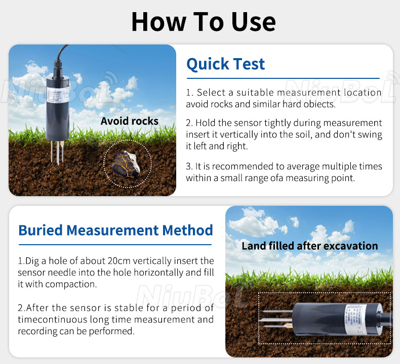
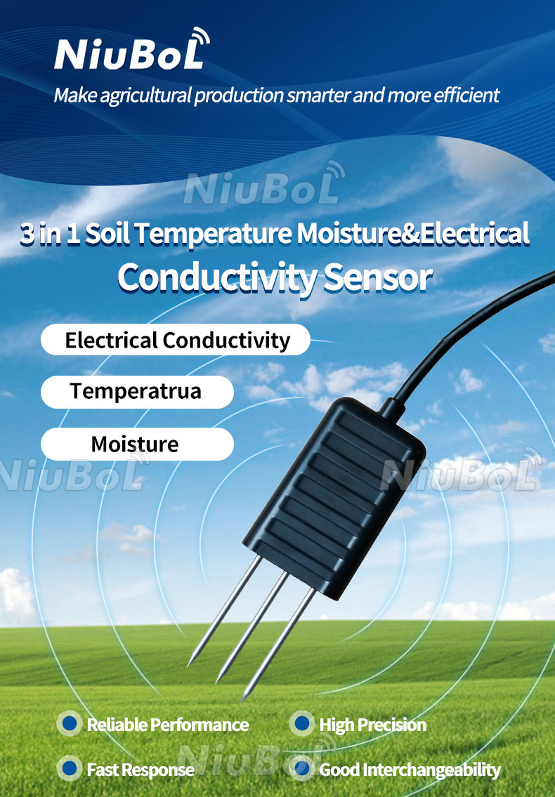
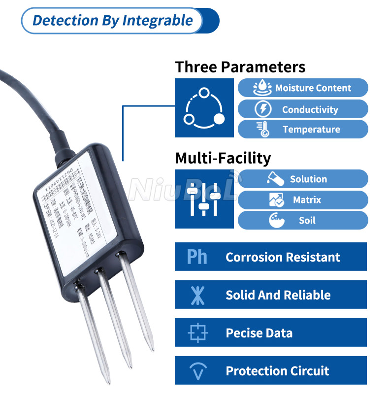
The NBL-S-TMC has a specified electrode length of 50 mm and measures moisture, temperature and EC. That dimension describes the probe, not a guarantee that its moisture value averages the whole 0-50 mm layer or any other assigned profile. The installed sensing geometry and soil contact still matter.
The sensing field is also not a sharp plane with zero thickness. Avoid assigning an exact sampled soil volume or clearance distance without instrument-specific evidence. Identify the installed section clearly while recognizing that it observes nearby material rather than every root in a stated depth band.
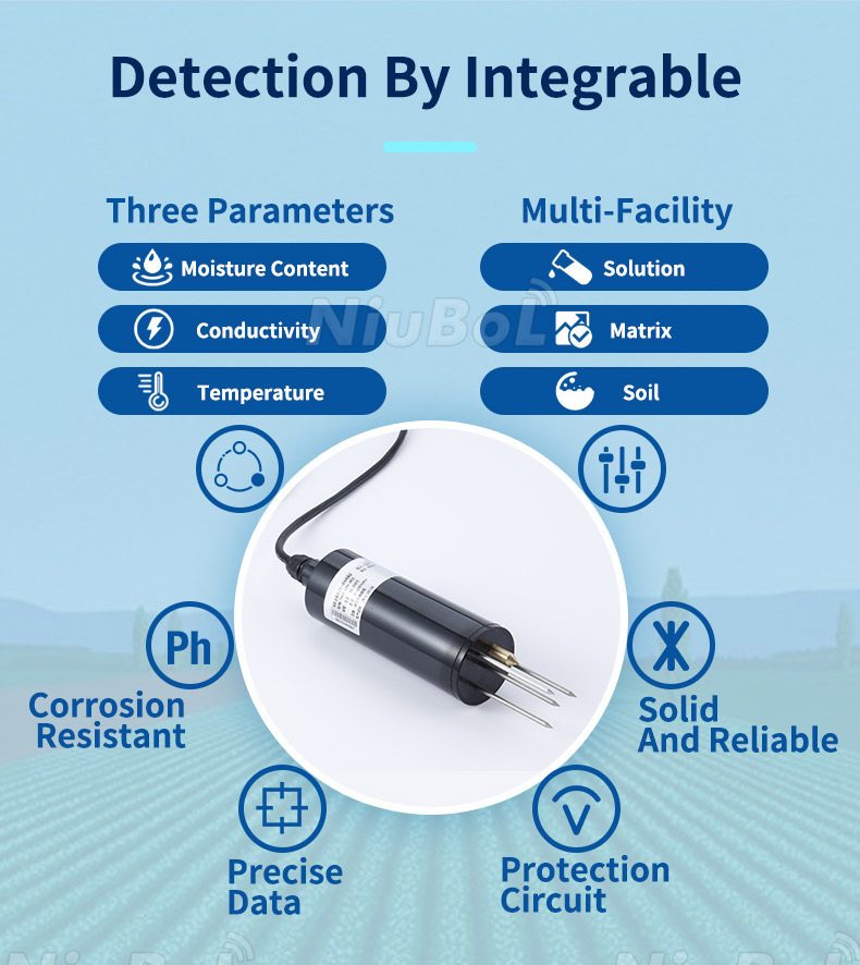
A vertically inserted pin probe can extend through a depth interval. For a fixed point at a chosen layer, a permitted horizontal sidewall installation can keep the electrodes near that level. Follow the supplied model's installation procedure; do not combine vertical insertion and parallel-to-ground instructions as though they describe one orientation.
| Drawing item | What to show | Confusion prevented |
|---|---|---|
| Surface datum | The ground or bed reference used for depth | Measuring from different surfaces |
| Active section | Its position and orientation | Treating housing or tip depth as the measurement depth |
| Installation form | Temporary insertion or permitted fixed burial | Copying a spot-check arrangement into an unattended point |
| Channel identity | Point, model and depth label | Swapping shallow and deep records at the logger |
| Emitter relation | Horizontal position relative to water delivery | Comparing different wetting positions as equal depth observations |
Crop rooting, growth stage, soil horizons and the intended decision determine useful observation positions. A shallow establishment question and a deeper root-zone question need not use the same depth. An arbitrary rule that every probe must be at least 30 cm deep can miss the very condition the project needs to observe.
A point at 30 cm is not automatically an average of the soil above it. For a profile calculation, define which layers the observations can reasonably represent. Use soil moisture profile interpretation for combining depth-specific observations without assuming equal water content throughout the root zone.

The NBL-S-THR provides moisture and temperature through its selected RS485 Modbus RTU or analog output. Several measurements at one point are not several soil depths. Adding EC with a TMC changes the channel set, not the number of layers observed.
For multiple probes, connect each device or input to a labelled physical position. Verify the mapping at the data logger or PLC before burial is completed. A software list sorted by Modbus address may not follow shallow-to-deep order; do not let that sorting silently define the soil profile.
Two instruments installed at the same depth can observe different wetting patterns if one is beneath an emitter and the other is between rows. Record horizontal position as well as depth. The intended comparison may require both points, but their different roles should remain visible.
Soil horizons also matter. The same distance below the surface may fall in different material across a field. Compare the soil description and local rooting conditions before interpreting a difference as sensor error or adjusting the entire irrigation zone from one reading.
Bed reshaping, hilling, erosion or added growing material can change depth relative to the current surface without moving the probe. Record the change and determine whether the point still serves the intended question. Do not quietly retain the old depth label if it now describes a different relationship to the crop.
Conversely, removing and reinstalling a probe to restore a nominal depth creates a new installation condition. Preserve the intervention date and previous geometry. Readings before and after the work may not be directly interchangeable even when the channel name and electronics are unchanged.

Specify the model, permitted orientation, reference surface, active-section depth, emitter relation and cable route. Photograph the placement against a visible depth reference before backfilling. Verify the recorded labels and save enough information to locate the point later without pulling on its cable.
For the full contact and burial procedure, see soil sensor installation guidance. Send NiuBoL the soil profile, desired observation depths and irrigation layout when requesting probe and acquisition options. Keep the agronomic depth decision separate from the supplied electrode dimensions.
Not necessarily. Locate the active measuring section and its orientation relative to the defined surface. Tip depth alone may describe a different part of the instrument.
No. Select observation positions from the crop, stage, soil profile and management question. A universal minimum can miss shallow conditions or place a probe below the relevant roots.
No automatic layer-average interpretation follows from that dimension. It describes hardware geometry. Field representation and any layer calculation require separate justification.
No. Moisture, temperature and EC are different quantities at the same installed point. Additional depths need the appropriate additional observation positions or a configured profile instrument.
Recheck the surface reference, current depth and relationship to the crop and emitter. Record any relocation or relabelling so the history does not conceal a changed observation geometry.
Check the installed model's orientation, connections and output definitions before field work.
 NBL-S-THR-Soil-temperature-and-moisture-sensors-Instruction-Manual-V4.0.pdfNBL-S-TMC-Soil-temperature-and-moisture-conductivity-sensor.pdfNBL-S-TM-Soil-temperature-and-moisture-sensor-Instruction-Manual-4.0.pdfNBL-S-TMCS-Soil-Temperature-Humidity-Conductivity-and-Salinity-Sensor.pdf7-in-1-Soil-Composite-Sensor-Manual.pdf8-in-1-Soil-Composite-Sensor-Manual.pdf
Specify soil moisture sensors for agriculture by the location of their active section, not a tip-depth label alone. Document the surface reference, orientation and emitter relation, and verify that the logger identifies the same point. Clear geometry makes later profile interpretation, service and replacement more dependable.
Prev:Construction Site Weather Station: Weather, Dust and Work Decisions
Next:Irrigation Soil Moisture Sensor: From Water Deficit to Refill Volume
Related recommendations
Sensors & Weather Stations Catalog
 Agriculture Sensors and Weather Stations Catalog-NiuBoL.pdf
Weather Stations Catalog-NiuBoL.pdf
Agriculture Sensors Catalog-NiuBoL.pdf
Water Quality Sensor Catalog-NiuBoL.pdf
Related products
 Combined air temperature and relative humidity sensor
 TDR Soil Moisture & Temperature Sensor for irrigation| RS485 |4-20mA| NBL-S-THR
 Soil pH sensor RS485 soil Testing instrument soil ph meter for agriculture |NBL-S-PH
 Wind Speed sensor Output Modbus/RS485/Analog/0-5V/4-20mA
 Tipping bucket rain gauge for weather monitoring auto rainfall sensor RS485/Outdoor/stainless steel
 Pyranometer Solar Radiation Sensor 4-20mA/RS485


Screenshot, WhatsApp to identify the QR code
WhatsApp number:+8615367865107
(Click on WhatsApp to copy and add friends)

