





— Blogs —
—Products—
 Consumer hotline +8618073152920
WhatsApp:+8615367865107
Address:Room 102, District D, Houhu Industrial Park, Yuelu District, Changsha City, Hunan Province, China
Product knowledge
Time:2025-02-14 16:33:29 Popularity:2330
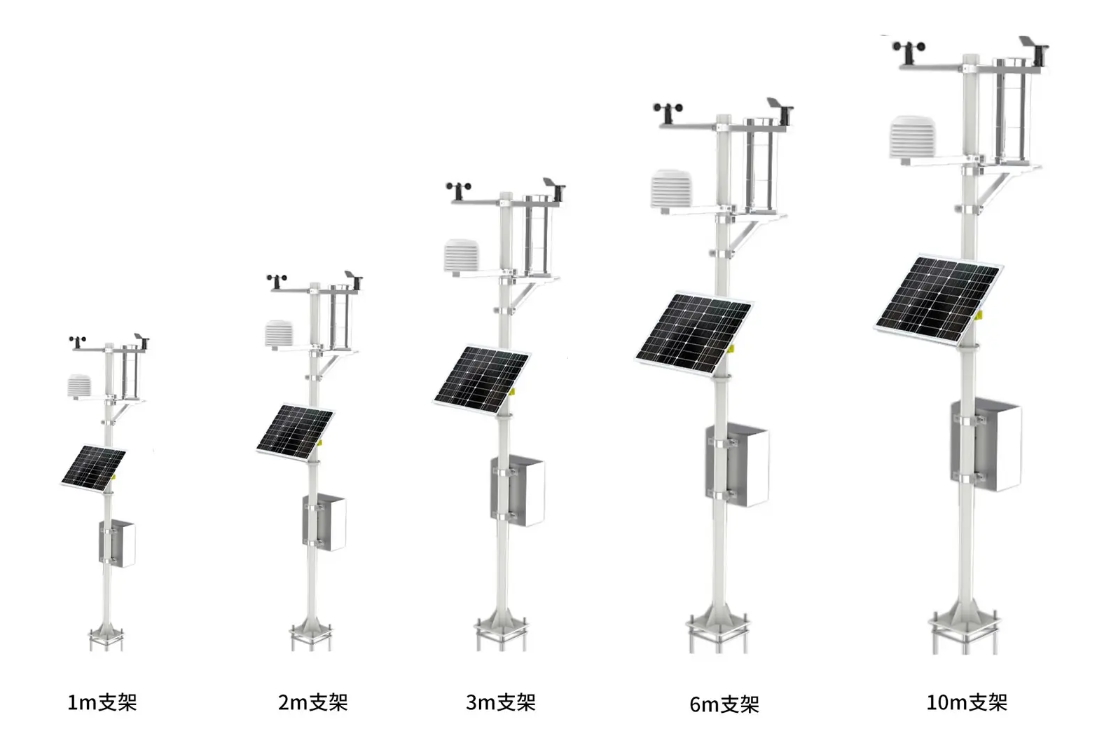
Solar weather station panel placement must provide usable sunlight without obstructing the measurements. Check shadows from the mast, crossarms, trees and nearby structures across the site's operating seasons. Keep the charging panel's position separate from the required exposure of wind, air and radiation sensors; one convenient mounting angle does not serve every component.
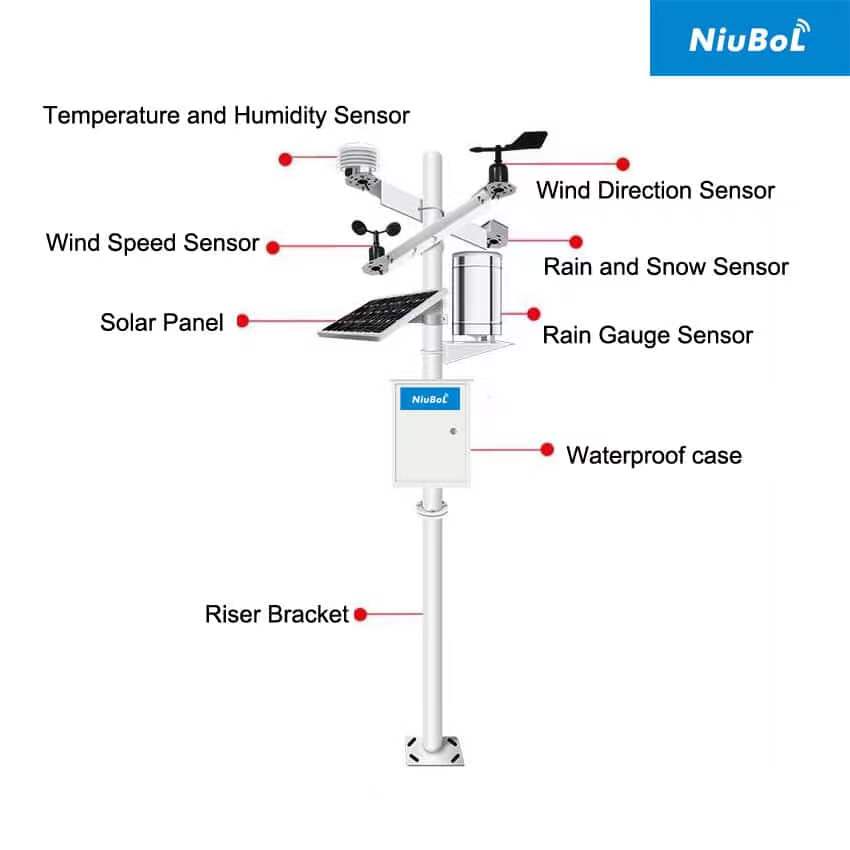
A solar-powered meteorological station uses a photovoltaic module to supply energy through a suitable charging and storage arrangement. It does not become independent of site conditions simply because a panel is fitted. A clear view at midday during installation can conceal morning shadows, winter obstruction or vegetation that will grow across the panel later.
Begin with the station's required observation location and a sketch of nearby obstacles. Examine the panel's proposed position at relevant times of day and consider seasonal changes in sunlight. The energy design should use site-appropriate solar information and the actual load. The placement survey helps identify avoidable shade; it does not establish battery autonomy by itself.
| Possible obstruction | What to examine | Practical response |
|---|---|---|
| Mast and crossarms | Moving shadows across the active module surface | Adjust the panel position or bracket without disturbing sensor exposure. |
| Trees and crops | Seasonal foliage, growth and maintenance access | Allow for the mature vegetation and a realistic inspection plan. |
| Buildings, fences or terrain | Obstruction during the site's useful charging period | Review another panel location or the power arrangement. |
| Panel surface contamination | Dust, leaves, bird deposits or snow accumulation | Provide safe access and a site-specific cleaning or inspection interval. |
The panel should not shed runoff into the rain collector, shelter wind instruments or obstruct a pyranometer's view. Its sun-heated surface and cabinet should also remain clear of the air sensor's ventilated sampling location. Check the whole assembly rather than evaluating the charging panel in isolation.
A separate panel mounting point may be appropriate when the observation mast cannot accommodate both functions. That option introduces cable routing, voltage-drop and mechanical requirements. Compare the complete arrangement, not just whether a panel can be attached to the existing pole.
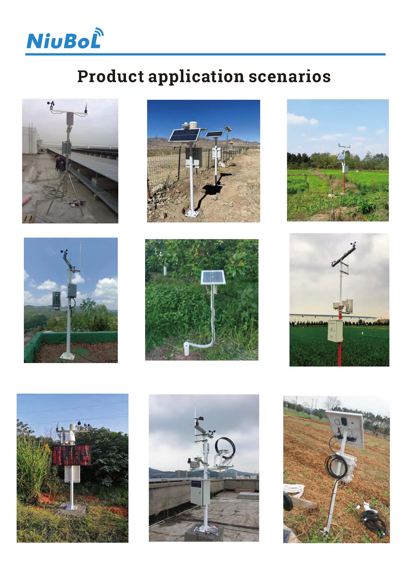
A photovoltaic supply panel is positioned to collect energy for the station. A NiuBoL NBL-W-HPRS pyranometer is positioned to measure the radiation plane specified by the observation task. Its 0-2000 W/m2 range describes irradiance measurement, not the power available to charge the battery.
The charging panel's tilt must not be copied automatically to a sensor intended to measure horizontal irradiance. Likewise, a solar-resource measurement does not show whether the charging circuit, battery and load are functioning. Keep the two purposes explicit on the installation drawing and in the maintenance record.
| Example component | Relevant specification | Power-layout check |
|---|---|---|
| NBL-W-LBTH | DC 12-24 V; RS485 Modbus RTU or 4-20 mA version | Provide the voltage required by the purchased version at its terminals. |
| NBL-W-SS | DC 5 V or DC 12-24 V, depending on output; approximately 50 mW; IP65 | Include the selected version, not an assumed common sensor supply. |
| TG462 / TG462S | DC 5-35 V input; IP30 device protection | Budget the configured logger and modem load and protect the device outdoors. |
| Panel, charger and battery | Selected for the project and battery type | Match electrical ratings, charge limits and site conditions before installation. |
A logger's wide input range does not mean all connected sensors can use the same unregulated voltage. Identify converters or regulated outputs where required. If the panel is moved farther away to avoid shade, check the routed cable length and electrical losses as part of the revised design.
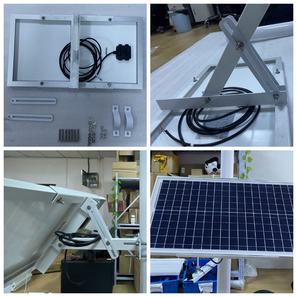
Use a bracket and foundation arrangement suitable for the actual panel area, mast and site loading. A larger replacement module can change the mechanical load even if the electrical system remains compatible. Confirm that adjustment and servicing do not rotate wind-direction instruments or disturb rain-gauge level.
Support the cable, protect it from sharp edges and movement, and provide suitable outdoor entries into the enclosure. Retain access to connectors and the panel surface. Installation sequence, polarity and isolation should follow the selected power equipment's procedure; a generic weather-station diagram is not a charging-controller wiring instruction.
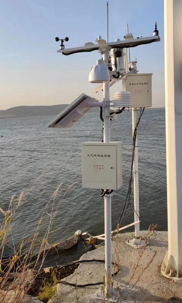
Solar weather station panel placement should be checked after the station is operating. Review charging behavior alongside sunlight, battery condition and the active loads, including communications. A normal-looking panel and a working dashboard at installation do not establish energy balance through a shaded or low-sun period.
Record the panel orientation, surrounding obstructions and any changes made during commissioning. Where low-voltage interruptions occur, investigate the load, charging route and battery condition as well as shade. Do not promise a fixed number of unattended days from the presence of a solar panel or an MPPT label.
No. Location, seasonal energy needs, obstruction and the selected mounting arrangement affect the choice. Use site-specific design information. The charging panel and radiation sensor may require different orientations because they perform different jobs.
Only if the arrangement preserves the collector's catch exposure and prevents panel runoff from entering it. Check the geometry and service access before accepting the shared mounting position.
It may remove one cause, but verify the cable route, charger configuration, battery condition and load as well. A longer cable can introduce additional losses, and a damaged battery will not be restored by changing panel position.
No. The panel surface, mounts, wiring, charging equipment and battery still require inspection. Sensor cleaning and measurement checks remain necessary regardless of the power source.
Send the site location, obstacle photographs, proposed mast arrangement, required measurements and power-load list. NiuBoL can review the station layout and identify whether a shared or separate panel mounting arrangement is appropriate.
Solar weather station panel placement is both an energy and measurement-layout decision. Avoid unnecessary shade, preserve sensor exposure and verify the electrical route under load. A site drawing and the actual component list provide a more useful starting point than a blanket promise of solar self-sufficiency.
Prev:Forest Fire Meteorological Station Alerts: Roles and Limits
Next:PV Weather Station Response Time: Sensor Lag or Data Delay?
Related recommendations
Sensors & Weather Stations Catalog
 Agriculture Sensors and Weather Stations Catalog-NiuBoL.pdf
Weather Stations Catalog-NiuBoL.pdf
Agriculture Sensors Catalog-NiuBoL.pdf
Water Quality Sensor Catalog-NiuBoL.pdf
Related products
 Combined air temperature and relative humidity sensor
 TDR Soil Moisture & Temperature Sensor for irrigation| RS485 |4-20mA| NBL-S-THR
 Soil pH sensor RS485 soil Testing instrument soil ph meter for agriculture |NBL-S-PH
 Wind Speed sensor Output Modbus/RS485/Analog/0-5V/4-20mA
 Tipping bucket rain gauge for weather monitoring auto rainfall sensor RS485/Outdoor/stainless steel
 Pyranometer Solar Radiation Sensor 4-20mA/RS485


Screenshot, WhatsApp to identify the QR code
WhatsApp number:+8615367865107
(Click on WhatsApp to copy and add friends)

