





— Blogs —
—Products—
 Consumer hotline +8618073152920
WhatsApp:+8615367865107
Address:Room 102, District D, Houhu Industrial Park, Yuelu District, Changsha City, Hunan Province, China
Product knowledge
Time:2026-01-17 10:45:59 Popularity:688
Submersible level transmitter density correction is necessary when hydrostatic pressure is converted using a reference density different from the actual liquid. The probe measures pressure at its diaphragm; liquid height is a calculated result. For a NiuBoL tank or well project, establish the liquid, temperature, pressure reference and level datum before choosing the range or adjusting the displayed value. A stable signal can still represent the wrong height if those inputs are wrong.
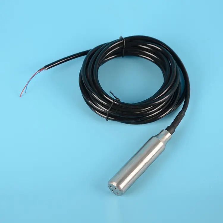
For an open vessel containing a reasonably uniform liquid at rest, the pressure difference associated with the liquid column is approximately delta P = density x gravitational acceleration x height. Height is measured above the sensing diaphragm, not automatically above the tank floor. If the probe is supported above the bottom, the controller needs the corresponding offset to report depth from the chosen tank datum.
A vented gauge-pressure probe references atmospheric pressure through its cable. This arrangement helps remove changes in external barometric pressure from the liquid-column result when the vent remains functional. It does not remove pressure above the liquid in a sealed or pressurized tank. In that application, headspace pressure must be accounted for using an appropriate measurement arrangement rather than interpreting every pressure change as added liquid.
Tank shape does not change the hydrostatic relation at a given height, but it does change the conversion from level to stored volume. A horizontal cylindrical tank requires a different volume function from a vertical rectangular vessel. Do not correct a volume error by changing density until the geometry, sensor elevation and units have been checked.
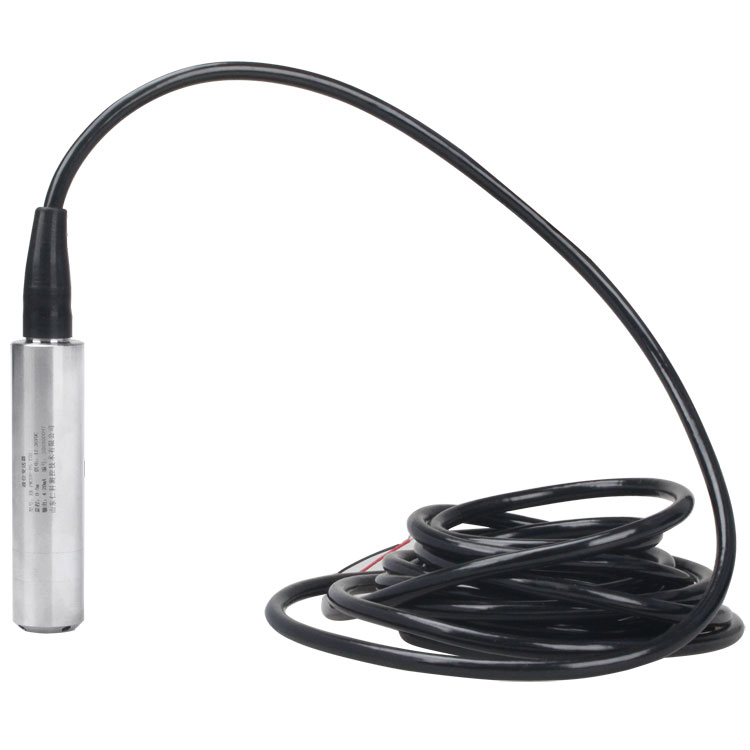
If a transmitter or controller reports a water-equivalent height using a reference density, the corrected height is indicated height x reference density / actual density. The actual density must represent the liquid at its operating temperature and composition. A generic description such as diesel, brine or wastewater is not enough to establish a fixed correction for every delivery or process state.
For illustration, suppose the reference density is 1,000 kg/m3 and the actual liquid density is 850 kg/m3. A true 2.00 m column produces a water-equivalent indication of 1.70 m. Correcting 1.70 x 1,000 / 850 gives 2.00 m. The 850 kg/m3 value is an example, not a specification for all oils. Verify the actual process density before applying it.
Apply the correction in one agreed location: instrument, PLC, logger or supervisory software. If the transmitter already reports density-corrected height, dividing again in the cloud creates a second error. Record the reference density, correction owner and software revision with the channel. Keep pressure, water-equivalent height and corrected process level distinctly labelled where more than one is retained.
| Process condition | Information required | Reason a fixed factor may fail |
|---|---|---|
| Changing concentration | Density over the actual composition range. | One value may describe only one batch or treatment stage. |
| Changing temperature | Density at operating temperature and any adopted compensation method. | Electronic temperature compensation does not eliminate liquid-density change. |
| Layered or settling liquid | Vertical composition and solids behaviour. | Pressure reflects the overlying column, which may not have one uniform density. |
| Pressurized headspace | Gas pressure and a suitable reference arrangement. | A vented open-tank conversion includes the additional gas pressure. |
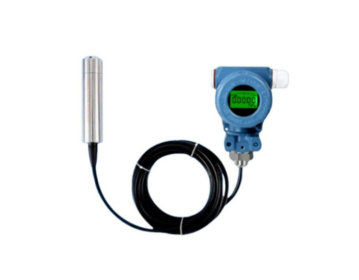
The NiuBoL NBL-L-WLPS submersible transmitter provides an RS485 Modbus RTU option for compatible acquisition equipment. Select its ordered pressure or level span using the maximum hydrostatic load, liquid density and pressure conditions. An unnecessarily wide span can increase the absolute uncertainty when accuracy is expressed as a percentage of full scale.
| RS485 NBL-L-WLPS configuration | Specification | Engineering consequence |
|---|---|---|
| Accuracy options | 0.5% FS default; 0.2% FS option | Convert percentage of full scale into an absolute pressure or level allowance. |
| Supply and power | DC 10-30 V, typical 24 V; maximum 0.2 W | Budget the separate logger and communications equipment as additional loads. |
| Output | RS485, Modbus RTU | Confirm register scaling, address and serial settings before deployment. |
| Circuit operating temperature | -20 to 80 degrees C for this configuration | Check the delivered version rather than extending a family-level temperature claim. |
| Long-term medium exposure | At or below 60 degrees C; liquid compatible with selected stainless steel | Temperature and chemical compatibility are separate selection checks. |
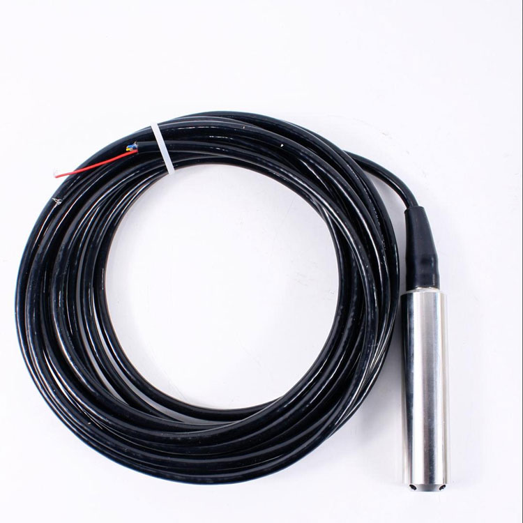
| Probe construction | IP68; approximately 26.8 mm diameter; vented cable | Protect the dry reference termination and verify mechanical clearance. |
A 0.5% FS specification on a 10 m span corresponds to 50 mm of equivalent full-scale level, while the same percentage on a 2 m span corresponds to 10 mm. These examples illustrate span selection; they do not include density, datum or installation uncertainty. Choose a span that covers the maximum pressure safely, then check whether the resulting absolute allowance supports the project decision.
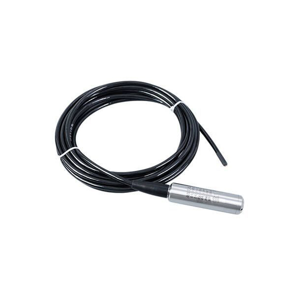
Compare against an independent level reference tied to the same datum. Record liquid temperature and process state at the time of comparison. A constant difference may be an elevation offset; a proportional difference may indicate density or scaling; an error that changes with weather may point to the pressure reference. These patterns guide investigation but do not identify the cause without further checks.
Keep the vent path dry and unobstructed. Crushing, tight bends or an incorrectly sealed termination can interfere with atmospheric reference. Do not cut or splice a vented cable merely to fit a cabinet without an approved arrangement that preserves both sealing and the reference path. Order the needed cable length and termination accessories where practical.
Sediment at the pressure inlet, direct pump suction and strong local motion can also affect the observation. Support the probe at a repeatable elevation with clearance suited to the actual deposits. A universal 10 cm offset is not a guarantee against burial, and moving the probe during cleaning requires the level datum to be rechecked.
A correct density factor does not make the probe chemically compatible. Provide chemical identity, concentration, temperature, cleaning agents and exposure duration when selecting wetted metals, seals and cable. Stainless steel and a named cable jacket are not blanket approvals for acids, alkalis, saline water or every oil formulation.
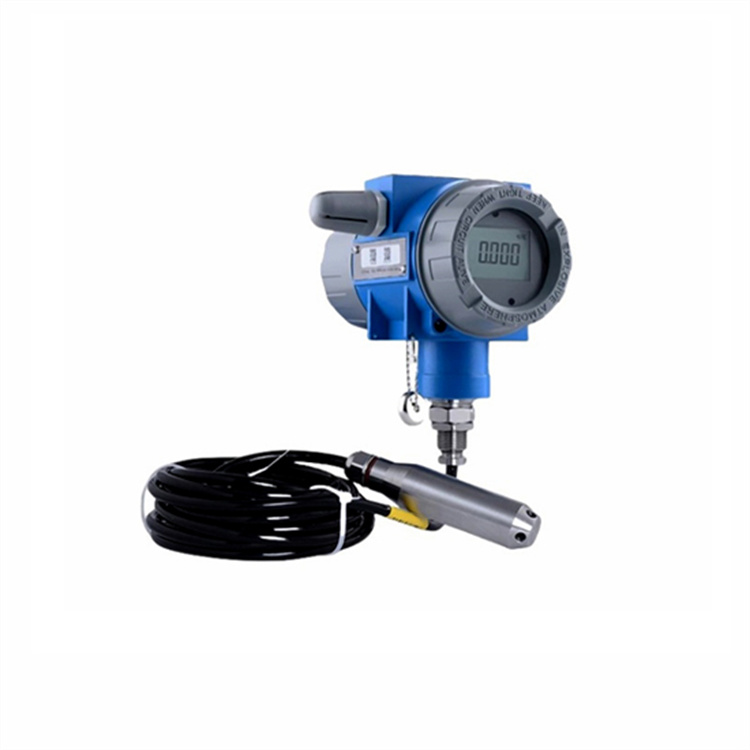
A split-type transmitter arrangement can provide a separate field housing for the selected installation, but its output, protection and any hazardous-location approvals must be checked on that exact model. A display or a metallic enclosure does not establish wireless connectivity or an approval for a particular hazardous area.
For an NiuBoL quotation, state maximum depth, density range, liquid temperature, headspace pressure, required absolute uncertainty, output and cable route. Identify whether the project needs pressure, corrected level or tank volume at the receiving system. Include the density source and who maintains the conversion so the delivered configuration can be checked against the actual process.
Pressure calibration may remain valid within the instrument's conditions, but converting that pressure to height requires the appropriate density. Material compatibility and pressure range also need separate confirmation.
Not necessarily. Sensor compensation addresses instrument behaviour; process-density compensation needs the relevant relationship or input. Confirm which quantity the selected model actually corrects.
Check the diaphragm elevation, datum, density and any headspace pressure. The probe reports the column above its sensing position; it does not automatically measure total depth from the floor.
No. A full-scale percentage refers to the selected span. At low operating level, its absolute allowance does not shrink in proportion to the reading.
No. Restore the correct reference path and investigate the affected data. Changing density or offset to mask a vent fault can make the reading wrong under other pressure conditions.
Only if that value adequately represents the overlying column and operating variation. Settling and composition changes can invalidate a single factor; assess the process before relying on one level conversion.
Submersible level transmitter density correction should make a pressure measurement interpretable, not conceal an offset, vent fault or incompatible application. Select the NiuBoL pressure span and wetted construction for the process, define the datum, and apply a verified density relationship once. Keep the calculation traceable through the PLC or logger so future process changes can be assessed without guessing.
Prev:Radar vs Submersible Water Level Sensor for Rivers: Field Selection
Next:Wireless Level Meter Selection: Coverage and Platform Acceptance
Related recommendations
Sensors & Weather Stations Catalog
 Agriculture Sensors and Weather Stations Catalog-NiuBoL.pdf
Weather Stations Catalog-NiuBoL.pdf
Agriculture Sensors Catalog-NiuBoL.pdf
Water Quality Sensor Catalog-NiuBoL.pdf
Related products
 Combined air temperature and relative humidity sensor
 TDR Soil Moisture & Temperature Sensor for irrigation| RS485 |4-20mA| NBL-S-THR
 Soil pH sensor RS485 soil Testing instrument soil ph meter for agriculture |NBL-S-PH
 Wind Speed sensor Output Modbus/RS485/Analog/0-5V/4-20mA
 Tipping bucket rain gauge for weather monitoring auto rainfall sensor RS485/Outdoor/stainless steel
 Pyranometer Solar Radiation Sensor 4-20mA/RS485


Screenshot, WhatsApp to identify the QR code
WhatsApp number:+8615367865107
(Click on WhatsApp to copy and add friends)

