





— Blogs —
—Products—
 Consumer hotline +8618073152920
WhatsApp:+8615367865107
Address:Room 102, District D, Houhu Industrial Park, Yuelu District, Changsha City, Hunan Province, China
Product knowledge
Time:2026-03-26 11:08:06 Popularity:798
An ultrasonic automatic weather station can remain connected while its wind channel is unavailable or unsuitable for use. The first diagnostic task is to distinguish a communications fault, an invalid acoustic measurement and a valid observation of light wind. Treating all three as zero wind can hide a fault precisely when a project needs dependable wind information.
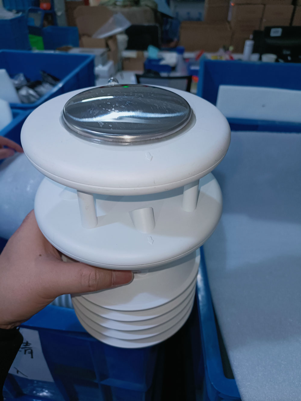
If every channel disappears, investigate the common power supply, serial connection, logger and network path. If temperature and pressure continue but wind stops updating, investigate the wind measurement and its mapping. Continued communication with a combined head does not prove that each sensing channel is valid.
Check the observation time, not only the time the dashboard refreshed. A platform can repeatedly receive or display an old wind value. Compare the available local output and receiving record before replacing the sensor. Preserve the original values and service findings so the cause can be traced.
| Condition | Evidence to seek | Misleading interpretation |
|---|---|---|
| Valid light wind | Current valid observations consistent with the installed measurement and conditions | Assuming every zero or small value proves a healthy sensor |
| Unavailable wind measurement | Documented invalid value or quality information where provided | Converting it to a normal zero-speed observation |
| Stale value | Old observation time or repeated retained data after acquisition stops | Calling a fresh screen update a new measurement |
| Communications failure | Failed acquisition or missing replies at the relevant interface | Concluding that the acoustic path itself has failed |
Request the actual model's invalid-value definitions and available quality fields. Do not invent a universal Modbus fault code for all NiuBoL heads. If a selected output does not expose diagnostic status, acknowledge that limitation and define the additional checks needed by the project.
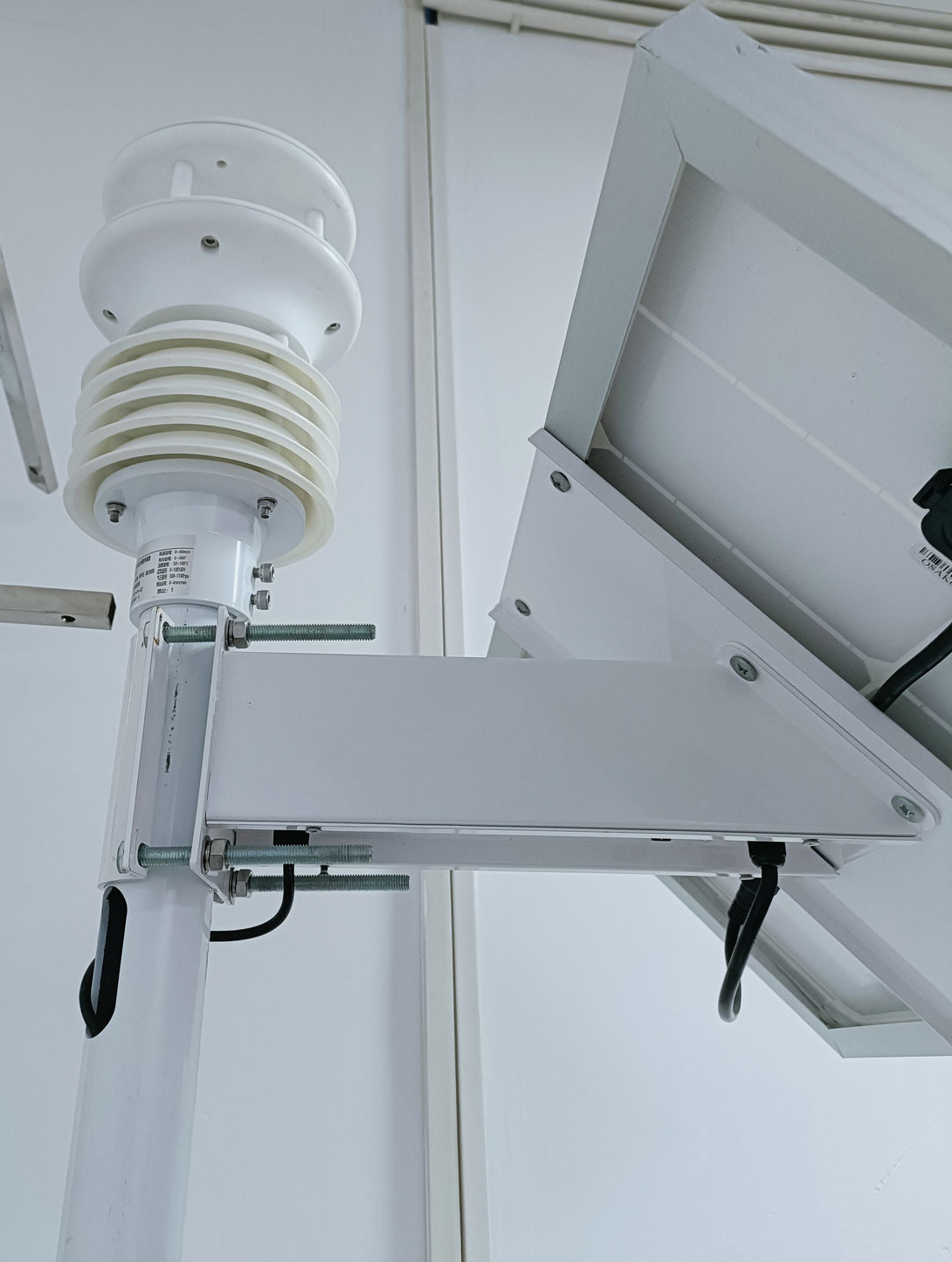
Ultrasonic wind sensing depends on sound travelling between transducers. Dirt, insects, nesting material or ice in that path can affect the observation. Inspect accessible surfaces and the supporting structure using the approved service procedure. No rotating cups does not mean that the head needs no inspection.
Do not insert tools between transducers, bend supports or use an improvised jet of compressed air to test the head. Follow the cleaning method for the selected assembly. Where access requires a lift or mast work, plan safe isolation and access rather than treating a compact sensor as a ground-level service item.

The NiuBoL NBL-W-71GUWS combines wind with selected weather measurements. A separate two-in-one wind head and a combined weather head can have different specifications and outputs. Read the model label and ordered configuration before using a parameter table or changing the logger setup.
| NBL-W-71GUWS item | Specification | Diagnostic consequence |
|---|---|---|
| Wind speed | 0-60 m/s; ±0.3 m/s + 3% F.S.; 0.01 m/s resolution | Display increments are not an installed accuracy test |
| Wind direction | 0-359°; ±3°; 1° resolution | Check orientation and valid data separately |
| Interface | RS485 Modbus RTU; 9600 bps | Confirm address, register mapping and reply interpretation |
| Supply | 9-24 V or 12-24 V version; average 0.4 W | Use the actual voltage version; sensor consumption excludes the station |
| Environment | IP65; -40 to 80°C; 0-95% RH | Not a claim of ice-free operation or unrestricted washdown |
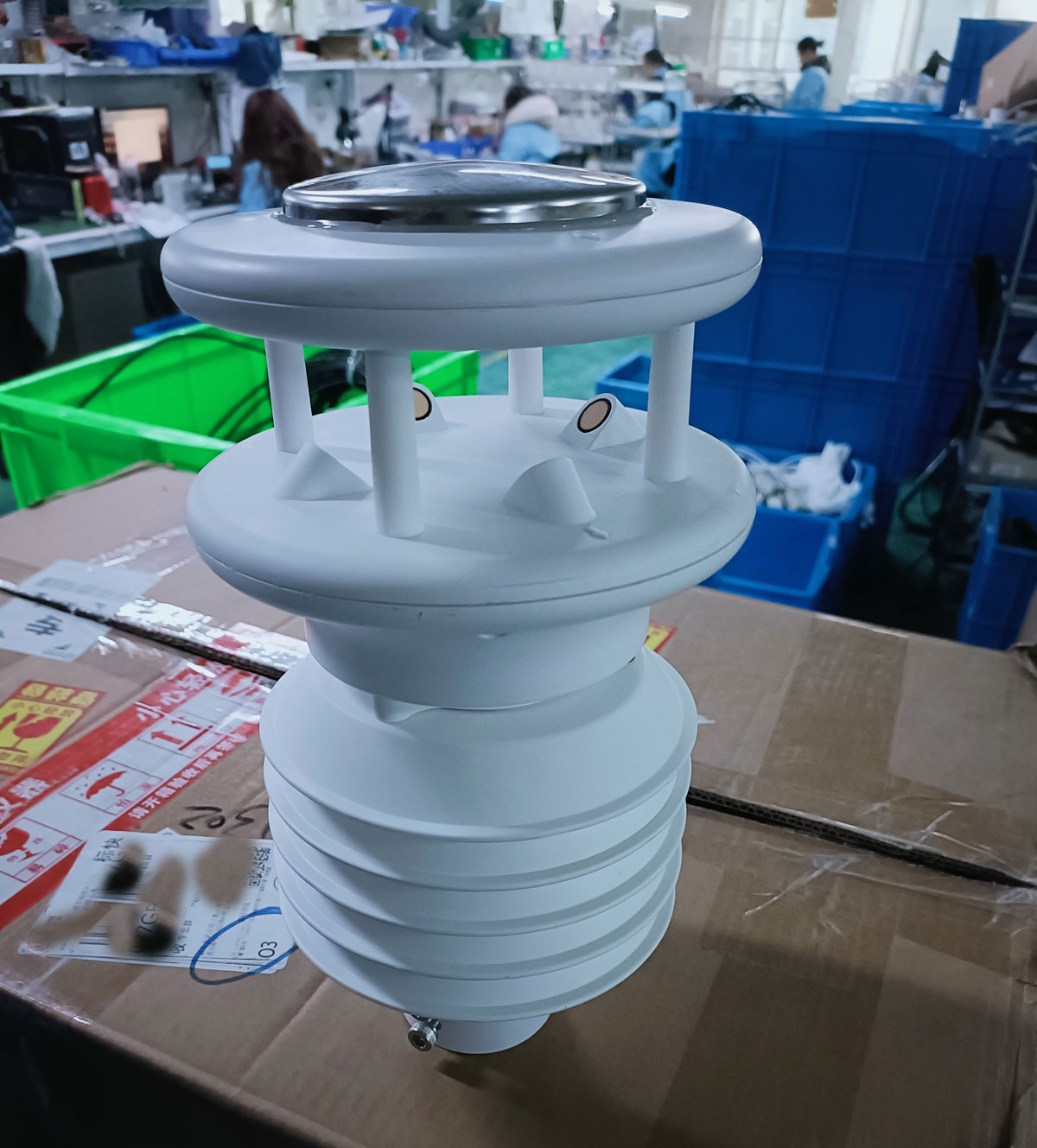
A suitable voltage at the cabinet does not establish the voltage at the end of the cable. Inspect supply and connections under the relevant operating condition. If other station loads start intermittently, determine whether their operation coincides with missing wind records or sensor restarts.
Heating, where offered for the selected head, is a separate option with its own electrical requirements. Do not assume that every ultrasonic sensor is heated or that a heater makes all data valid during icing. Identify the installed option and test its power and status as specified.
A replaced head or updated configuration can change the data arrangement. Verify that wind speed and direction use the correct registers, units and scaling. Check whether the receiving system treats a timeout, an invalid response or a sign/format error as a numeric observation.
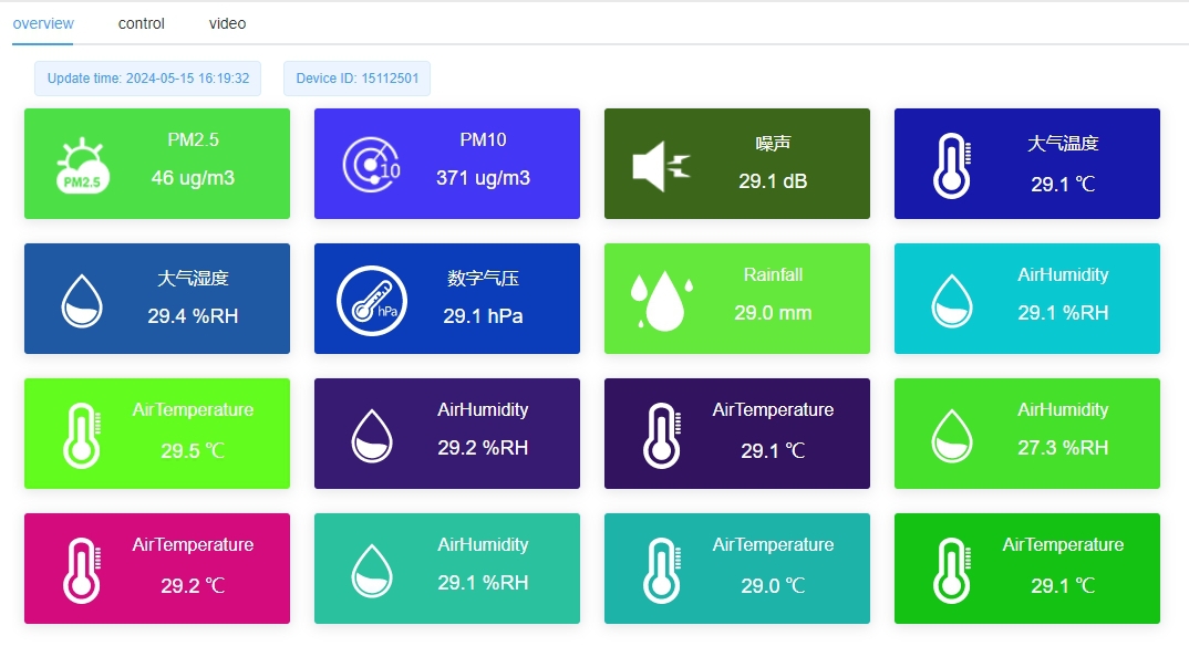
Compare a direct read with the logger and platform during the same check. If the direct observation updates while the platform retains one value, the fault may be downstream of the head. A complete reply frame is not enough: confirm that the values being stored are the intended channels.
A nearby building, mast or mounting arm can disturb the airflow seen by the head. Wind from one sector may behave differently from another. Compare the installation and direction of the suspected interference before changing calibration or applying a software correction.
Similarly, a nearby comparison instrument can see different air if its height or position differs. Agreement under calm conditions does not establish agreement across the operating range. Use an appropriate comparison arrangement and retain its limitations instead of declaring either instrument correct from a single reading.
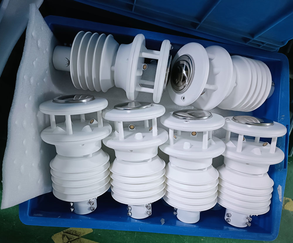
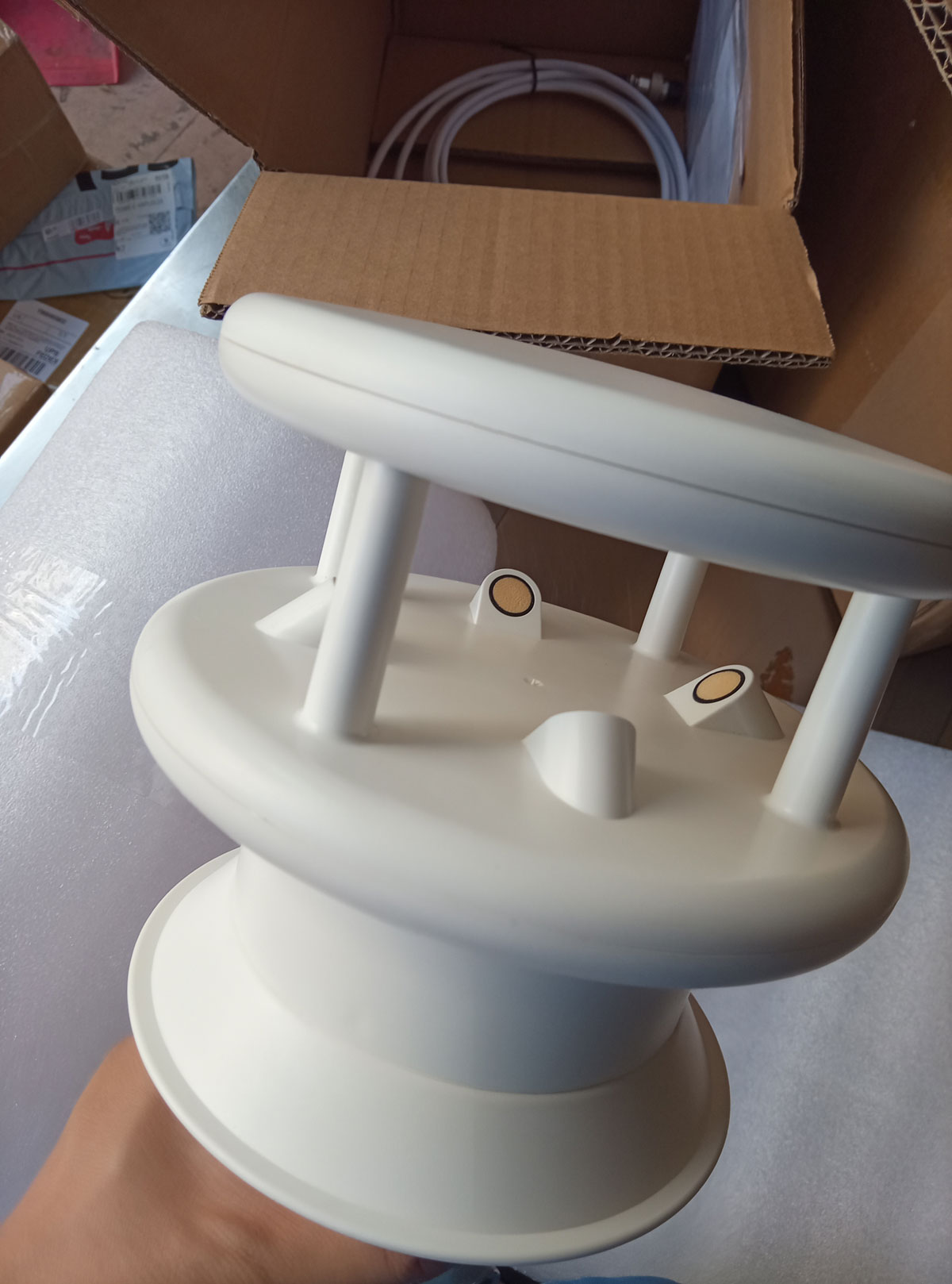
The horizontal transducer arrangement supplies horizontal wind speed and direction. It does not acquire vertical velocity merely because the station has additional temperature, humidity or pressure channels. A project requiring three-dimensional flow or turbulence needs an appropriate measurement arrangement and data specification.
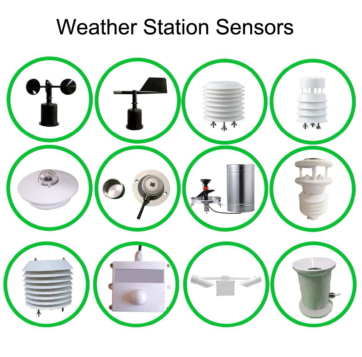
Ultrasonic describes the wind method, not every channel in a combined weather station. Rainfall, atmospheric sensing and light measurements have their own methods and fault conditions. A functioning rain channel cannot validate the wind channel, and a wind fault does not automatically invalidate an independent rain observation.
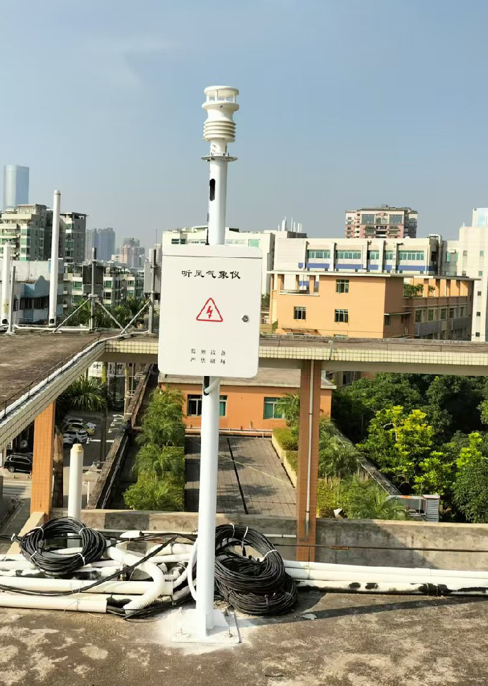
After cleaning, rewiring or configuration correction, confirm current local and remote observations, valid-value handling and the resolved fault. Remove any test values from operational use while retaining the service note. If the cause remains unresolved, mark the channel accordingly rather than forcing its output into an expected range.
Send NiuBoL the exact head model, output version, raw reply or error, supply measurements, time of the problem and photographs of the installation. Describe whether other channels continued. This evidence helps distinguish a replacement requirement from a wiring, mapping or exposure problem without assuming an entire station must be replaced.
No. Communications can continue while a sensing channel is invalid or stale. Check the wind observation time, the model's available diagnostic information and the local output.
No. A valid zero-speed observation and unavailable data have different meanings. Preserve the documented invalid or missing state in the receiving system.
The absence of rotating parts removes some mechanical service tasks, but acoustic paths, mounting, cables and exposed surfaces still need inspection. Plan service around the actual site and instrument rather than a universal multi-year interval.
It cannot create an independent vertical velocity observation from channels that do not measure it. Identify a suitable three-dimensional instrument if that quantity is required.
Confirm the model, supply at the head, interface and mapping, current raw output, physical condition and exposure. A working replacement will not correct an unchanged downstream mapping error or obstructed installation.
Diagnosing an ultrasonic automatic weather station starts by separating measurement validity from communications and display behavior. Check the acoustic path, actual power and data mapping before replacing hardware. NiuBoL integrated and separate heads should be assessed against their own configurations, with missing wind kept distinct from valid calm conditions.
Prev:Pest Monitoring System Data Integration: Link Images, Counts and Status
Next:Agricultural Four-Conditions Monitoring: Specify the Crop Camera Output
Related recommendations
Sensors & Weather Stations Catalog
 Agriculture Sensors and Weather Stations Catalog-NiuBoL.pdf
Weather Stations Catalog-NiuBoL.pdf
Agriculture Sensors Catalog-NiuBoL.pdf
Water Quality Sensor Catalog-NiuBoL.pdf
Related products
 Combined air temperature and relative humidity sensor
 TDR Soil Moisture & Temperature Sensor for irrigation| RS485 |4-20mA| NBL-S-THR
 Soil pH sensor RS485 soil Testing instrument soil ph meter for agriculture |NBL-S-PH
 Wind Speed sensor Output Modbus/RS485/Analog/0-5V/4-20mA
 Tipping bucket rain gauge for weather monitoring auto rainfall sensor RS485/Outdoor/stainless steel
 Pyranometer Solar Radiation Sensor 4-20mA/RS485


Screenshot, WhatsApp to identify the QR code
WhatsApp number:+8615367865107
(Click on WhatsApp to copy and add friends)

