





— Blogs —
—Products—
 Consumer hotline +8618073152920
WhatsApp:+8615367865107
Address:Room 102, District D, Houhu Industrial Park, Yuelu District, Changsha City, Hunan Province, China
Product knowledge
Time:2025-01-16 11:51:56 Popularity:1614
An ultrasonic snow depth monitoring station calculates snow depth relative to a reference surface. If the sensor support moves while the stored reference remains unchanged, the reported depth can change even when the snow does not. Establish the snow-free reference, maintain vertical alignment and verify the reference after any mounting-height change; automatic physical leveling should not be assumed.
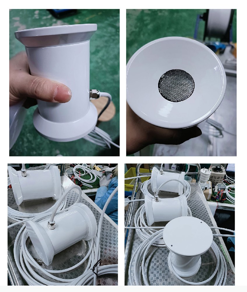
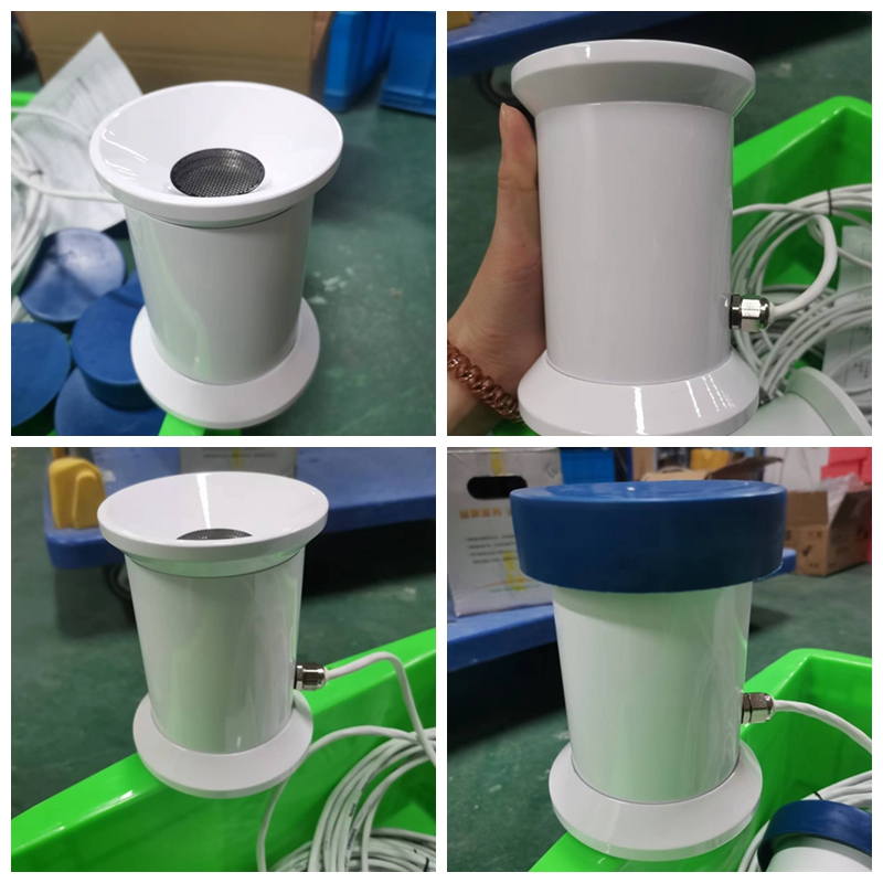
The NiuBoL NBL-W-SNOW ultrasonic snow depth sensor uses a 50 kHz acoustic signal to measure the distance to the reflecting surface below it. The monitoring system derives snow depth from the difference between the established reference distance and the current distance to that surface.
In a simplified example, a snow-free reference distance of 1300 mm and a current distance of 1100 mm indicate 200 mm of snow depth. These are illustrative distances, not a measured site result. The installation must also remain within the selected instrument's measurement and clearance requirements.
A zero established over existing snow is a different baseline from bare ground. If the system treats that surface as zero, its later record describes changes relative to the selected surface rather than the complete snow cover above the original ground. Record the reference condition before interpreting the series.
| Parameter | Specification | Practical meaning |
|---|---|---|
| Principle and frequency | Ultrasonic time-of-flight; 50 kHz | The acoustic path and reflecting surface must remain suitable |
| Snow-depth range and stated accuracy | 0-1000 mm; +/-0.1% FS | Does not remove installation or reference-height error |
| Supply and power | DC 12 V; approximately 180 mW normally; approximately 3 W with low-temperature heating | Budget winter heating separately from normal consumption |
| Environment and protection | -40 to 50 C; IP66 | Assess the whole installed assembly and keep the acoustic opening clear |
| Cable and interface | Standard cable 5 m; RS485; default 9600 bps | Match the receiving system and actual cable route |
| Typical installation position | Approximately 1.3 m +/-0.1 m above the reference surface | Set the reference for the actual installed position |
The stated percentage of full scale is an instrument specification, not a guarantee that an installed mast and changing surface will produce the same total uncertainty. A stable reference and correct geometry are essential even when the sensor itself is within specification.
A compatible NiuBoL collector can establish the reference height through its configured snow-detection setup. That is a data operation. It does not physically straighten the mast, move the sensing head or guarantee that the sensor points at the intended patch of ground.
Mount the acoustic face vertically toward a clear, representative surface. Avoid vegetation, stones, equipment and unintended objects within the measurement area. The installation should not substitute an unusual drift pocket or scoured patch for the surface the project intends to observe.
Reference-setting does not compensate for an unsuitable mounting arrangement. Follow the setup procedure for the actual sensor and collector configuration, and recheck the reference whenever the mounting height is adjusted.
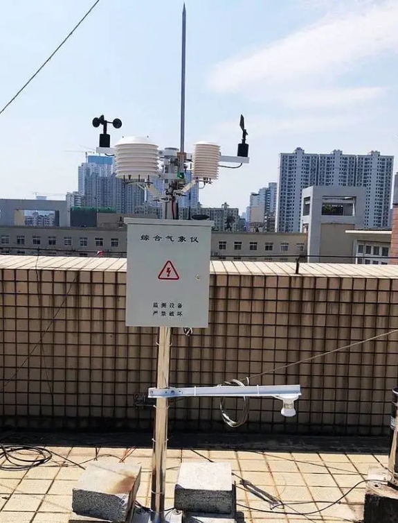
Using the simplified 1300 mm reference again, suppose the support moves downward by 20 mm while the snow surface remains unchanged. The measured distance falls by 20 mm. If the software continues subtracting that distance from the old reference, reported snow depth rises by 20 mm without additional snow.
An upward shift creates the opposite bias. Tilting can also change the acoustic path and the surface being sampled. These effects cannot be corrected simply by cleaning the transducer or verifying that an RS485 reply is received.
Investigate an abrupt depth step against service records, support condition, reference settings and actual surface conditions. Do not force a suspicious value to zero while snow is present merely to make the chart look normal. Establish the physical cause and document any necessary reference change.
The standard NBL-W-SNOW documentation identifies an NBL private protocol over RS485. Although the read framing resembles familiar industrial messages, it should not be treated as a universal standard Modbus RTU device without confirmation of the supplied version. Obtain the matching communication document and receiver support before ordering.
Also confirm whether the receiving record contains the measured distance or a snow depth already calculated by the collector. Applying reference subtraction twice, or treating a distance value as depth, can invert the intended result. Verify the unit and scaling with a known interpretation at commissioning.
The matching collector can also use a temperature-dependent snow-display setting. A value hidden by the configured temperature condition is not proof that the sensor measured zero snow. Keep acquisition, calculation and display behavior distinguishable when investigating an empty or changing chart.
Inspect mounting stability and the acoustic opening before the snow season. Heating associated with low-temperature operation helps limit frost or icing around the sensing area, but it does not prevent every obstruction or make winter maintenance unnecessary. The heater's approximately 3 W demand also matters to the power arrangement.
After work on the support, verify orientation and reference position before using the resumed record. If a different reference must be established, record when and why it changed. Retain the earlier data with its original context rather than presenting two different baselines as an uninterrupted physical observation.
For an ultrasonic snow depth monitoring station enquiry, give NiuBoL the maximum expected snow cover, reference surface, proposed mounting arrangement, winter power, cable route and required protocol. Depth alone does not establish fresh snowfall, water equivalent, roof load or avalanche risk; include those separate requirements when relevant.
Do not assume that function. Establishing a reference value in a collector is different from mechanical leveling. The installation must remain correctly aligned and stable.
In the simplified vertical geometry, yes: a 20 mm change in distance with an unchanged stored reference appears as a corresponding depth change. Confirm the actual geometry and cause before correcting data.
That can establish a new baseline at the existing surface rather than the original ground. Follow the supported procedure and record the reference condition; do not interpret the resulting series as unchanged total snow depth.
No. The standard documentation identifies an NBL private protocol. Confirm a compatible receiver or an explicitly supported protocol configuration instead of assuming direct compatibility from the interface alone.
Include the stable support, reference arrangement, compatible collector, cable, winter power and required remote connection. Specify commissioning and reference-setting responsibilities, especially when the installed geometry may change during service.
An ultrasonic snow depth monitoring station depends on a stable, documented reference as much as a working sensing head. Keep installation geometry, measured distance, calculated depth and display settings clear. Verify the baseline after support work so a mechanical shift does not become a fictitious snowfall event in the record.
Prev:Vibrating Insecticidal Lamps: Light Attraction and Electric-Grid Capture
Next:Smart Weather Station Configuration Changes: Tests After an Update
Related recommendations
Sensors & Weather Stations Catalog
 Agriculture Sensors and Weather Stations Catalog-NiuBoL.pdf
Weather Stations Catalog-NiuBoL.pdf
Agriculture Sensors Catalog-NiuBoL.pdf
Water Quality Sensor Catalog-NiuBoL.pdf
Related products
 Combined air temperature and relative humidity sensor
 TDR Soil Moisture & Temperature Sensor for irrigation| RS485 |4-20mA| NBL-S-THR
 Soil pH sensor RS485 soil Testing instrument soil ph meter for agriculture |NBL-S-PH
 Wind Speed sensor Output Modbus/RS485/Analog/0-5V/4-20mA
 Tipping bucket rain gauge for weather monitoring auto rainfall sensor RS485/Outdoor/stainless steel
 Pyranometer Solar Radiation Sensor 4-20mA/RS485


Screenshot, WhatsApp to identify the QR code
WhatsApp number:+8615367865107
(Click on WhatsApp to copy and add friends)


