





— Blogs —
—Products—
 Consumer hotline +8618073152920
WhatsApp:+8615367865107
Address:Room 102, District D, Houhu Industrial Park, Yuelu District, Changsha City, Hunan Province, China
Product knowledge
Time:2025-04-02 11:51:10 Popularity:1776
Reservoir water and rainfall monitoring measures local conditions that can support storage accounting. Water level becomes stored volume only through a suitable elevation-capacity relationship. Rainfall, discharge and water-quality measurements answer separate questions. A rain gauge and level sensor do not independently calculate reservoir inflow, authorize releases or establish dam condition.
A water-resource team may need current elevation, total storage, usable storage or a change in volume over a reporting period. These outputs are related but not interchangeable. A level reading in metres cannot simply be relabeled cubic metres, and the latest elevation alone cannot describe all inflows and withdrawals.
Record which survey reference, capacity relationship and reporting period the project will use. Identify whether the task is routine water accounting, event review or an operating warning. The instruments can supply observations for those tasks without being a complete reservoir operating system.
| Quantity | Typical unit | What is needed beyond the sensor value |
|---|---|---|
| Water elevation or depth | m or mm | Reference datum and the distinction between depth, distance and elevation |
| Stored volume | m³ | A site-specific elevation-capacity relationship |
| Rainfall depth | mm | Location, time interval and spatial representation |
| Discharge | m³/s | Validated velocity-area or another suitable flow method |
| Transferred water volume | m³ | Discharge integrated over the required period |
| Water-quality concentration | Parameter-specific units | A dedicated instrument and representative monitoring location |
Keep the units in the exported data, not only on the dashboard. An engineer combining observations from several devices needs to distinguish a pressure-derived depth from a surveyed reservoir elevation and a rate from an accumulated volume.
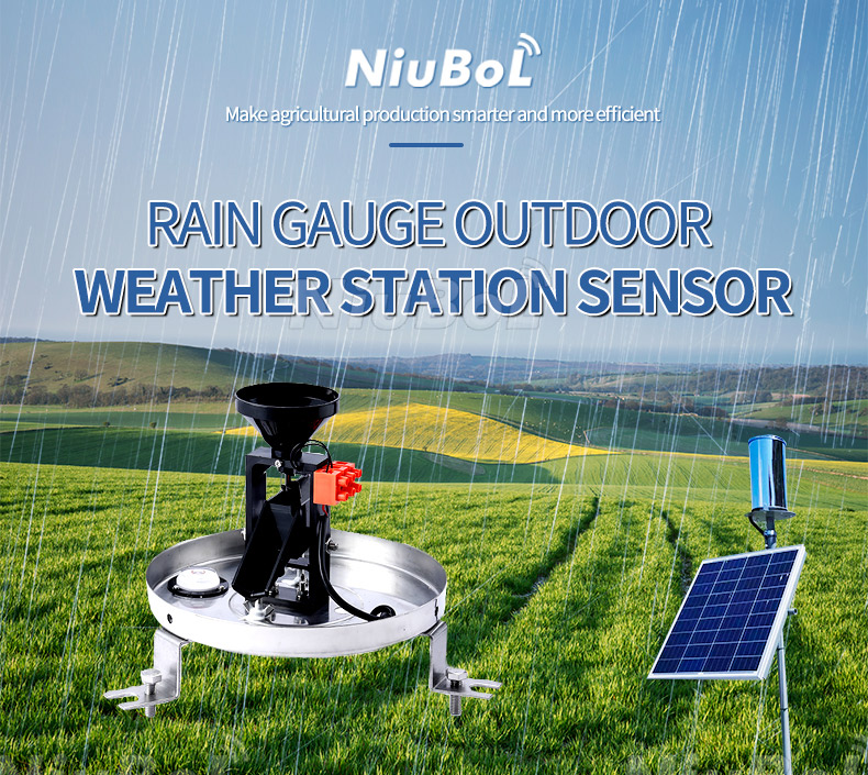
The NiuBoL NBL-W-RS records liquid rainfall at its collector. Rain over the upstream catchment can differ from rain beside the reservoir. Runoff also depends on the catchment and antecedent conditions, so multiplying one local reading by catchment area does not establish measured inflow.
For rainfall directly onto the reservoir surface, a depth-to-volume calculation needs an appropriate water-surface area and representative rainfall. That direct contribution is still different from catchment runoff. Keep any estimated term identified by its method instead of presenting every water-balance input as a sensor measurement.
| Example component | Selected specification | Accounting limitation |
|---|---|---|
| NBL-W-RS rain gauge | 0.2 mm increment; intensity 0-4 mm/min; ±4% in the specified indoor test at 2 mm/min | Point liquid rainfall, not direct inflow or a whole-catchment water volume |
| NBL-W-RS electrical/environmental options | DC 5 V or DC 12-24 V; switching, selected voltage or RS485 output; operating 0°C to 50°C | Select the receiving input and assess freezing separately. |
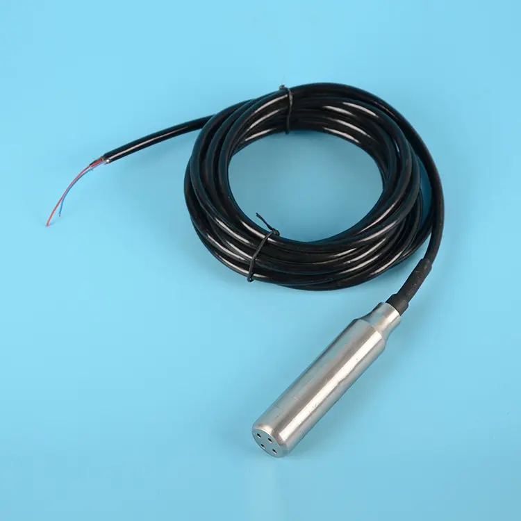
| Pressure-based level configuration | 0-1500 mm range; 0.1 mm resolution; stated accuracy ±0.5% at 0°C to 50°C; DC 12-24 V | A specified shallow-range option, not a universal reservoir-depth instrument |
A submerged pressure sensor determines a local water depth from pressure under the relevant density and pressure-reference assumptions. To obtain reservoir elevation, relate its installed position to the site's survey reference. Moving the probe or support changes that relationship even when the sensor still reports a plausible depth.
The linked 0-1500 mm configuration should be selected only where its span suits the intended depth variation and installation. Larger reservoirs do not make a shallow-range probe suitable for every mounting depth. Confirm the required range, output and pressure-reference arrangement rather than assigning an unnamed model a larger span.
Its available outputs include 4-20 mA, 0-5 V and RS485 versions. Confirm the delivered digital protocol and scaling; an RS485 connector alone does not establish the complete Modbus definition. Preserve the selected conversion with the level record.
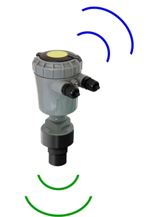
An overhead ultrasonic or radar level instrument measures the distance to the reflecting water surface. Reservoir elevation is derived from the surveyed instrument reference and that distance. It does not directly measure water depth to the bed or the stored volume.
Choose among the level measurement instruments according to high- and low-water distances, clearance, surface conditions, obstructions and access. Keep the measurement method and reference position with the data. Replacing a submerged probe with an overhead instrument changes the reference calculation, not merely the connector.
The USGS explanation of reservoir capacity describes building elevation-capacity relationships from surface areas at selected elevations, derived from bathymetric surveys or topographic information. That relationship is specific to the reservoir; a level sensor cannot discover it from one pressure or distance reading.
Keep the capacity table's datum, units, version and applicable range. Changes in sedimentation or reservoir geometry can affect storage at a given elevation. A high-resolution level value does not correct an outdated or mismatched capacity relationship.
The following hypothetical values illustrate a nonlinear capacity table. They are not a surveyed reservoir or a NiuBoL installation result.
| Water elevation | Stored volume | Change from the preceding row |
|---|---|---|
| 100.0 m | 1,000,000 m³ | Reference example |
| 100.5 m | 1,060,000 m³ | 60,000 m³ |
| 101.0 m | 1,125,000 m³ | 65,000 m³ |
Equal 0.5 m elevation increments produce different volume increments in this example. Do not use one fixed volume-per-metre factor across an entire reservoir unless its geometry and the adopted method justify that approximation.
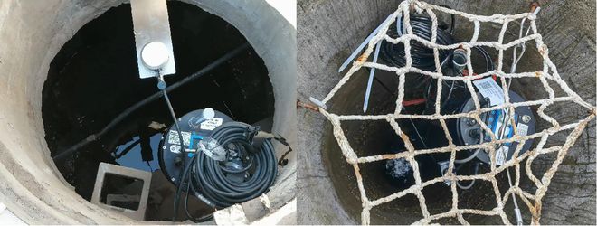
A confined installation, stilling arrangement or local channel can respond differently from the main reservoir surface. Confirm that the observed level represents the water body and accounting point intended. Protect the measurement from unsuitable local flow effects without assuming every protected enclosure creates an equivalent reservoir reference.
Retain independent reference checks and dated records of support movement, maintenance and replacements. If the reported elevation shifts after intervention, investigate the reference before interpreting the shift as a real gain or loss of stored water. Do not hide a datum correction inside an unexplained sensor offset.
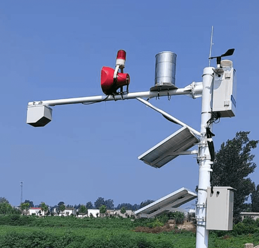
Solar radiation, air temperature, humidity and wind can provide inputs to a selected evaporation method. An ordinary atmospheric station does not automatically measure reservoir evaporation volume. Specify the calculation, required inputs, surface-area treatment and time interval before including that term in water accounting.
A modular weather station may supply those selected observations alongside rainfall. A missing radiation channel cannot be replaced by changing an illuminance label, and a general weather dashboard is not evidence that a validated reservoir-loss calculation is included.
Over a defined period, storage change reflects inflow, outflow, rain directly onto the surface, evaporation and other relevant gains or losses. To investigate an unexplained balance, compare quantities over the same interval and retain uncertainty or estimated status for each term.
A rise in storage is not necessarily the entire inflow: water may have left through an outlet during the same period. Conversely, a falling level does not identify whether withdrawal, evaporation, seepage or a reference error caused the change. The record supports an investigation; it does not diagnose every mechanism from level alone.
For reservoir water and rainfall monitoring, request a data structure that keeps measured elevation, calculated storage, rainfall and transferred volumes separate. Do not overwrite the original elevation series when a capacity table is revised; retain which calculation version produced each storage report.

Stored volume does not establish whether water is suitable for a particular use. Where the project needs pH, conductivity, dissolved oxygen or turbidity, use appropriate water-quality sensors and a representative sampling or immersion arrangement. These quantities are not derived from rain or water level.
Keep their maintenance, calibration and validity separate from the quantity record. A healthy level channel cannot confirm that a fouled water-quality probe is valid, and a change in concentration does not by itself quantify the volume entering or leaving the reservoir.
A non-contact radar flowmeter can contribute level and surface-velocity observations to a configured flow calculation. Discharge requires the appropriate section geometry and velocity relationship. A surface velocity in m/s must not simply be relabeled m³/s.
Integrating a valid discharge gives transferred volume. For illustration, a constant 5 m³/s over one hour corresponds to 18,000 m³. A real changing flow needs the appropriate time integration. Keep outlet measurements, modelled discharge and commanded gate positions distinguishable; a command is not measured flow.
For an enquiry, provide reservoir references and ranges, available capacity information, rainfall coverage, proposed flow sections, power and communications. Ask NiuBoL to match sensors and the PLC, RTU or data logger interfaces. Reservoir releases remain subject to the responsible operator's approved procedures, not a generic sensor threshold.
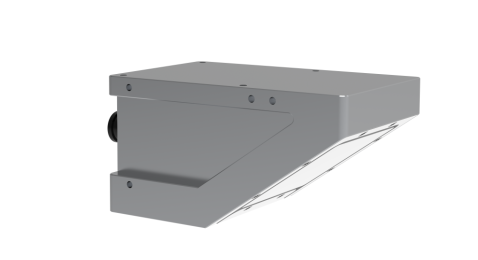
It supplies a level-related observation. Storage additionally requires an appropriate elevation-capacity relationship and common datum. Confirm where that calculation occurs and retain the original level record.
No. Local rainfall is a point observation; catchment rainfall and runoff can differ. Use appropriate inflow measurements or a defined hydrological estimate, with its assumptions identified.
No. Datum uncertainty, sensor accuracy and the capacity relationship also affect the result. A 0.1 mm displayed increment cannot establish the accuracy of the surveyed reservoir volume.
Not by itself. Use the appropriate cross-section geometry, water level and validated velocity conversion or flow method. Then integrate discharge over time if transferred volume is required.
Monitoring supplies observations and configured calculations. Release decisions require the site's approved operating rules, responsible personnel and the relevant downstream and forecast information. A sensor package alone does not provide that authority or complete control design.
Provide the required datum, expected water-level range, mounting location, power and data destination. State whether the deliverable is level, elevation, storage or discharge, because those require different reference information or instruments. Ask who will supply the elevation-capacity relationship and who is responsible for maintaining it.
Compare a known surveyed elevation and its capacity-table entry with the platform calculation, including the interpolation rule and datum. Repeat at another point if practical. A correct sensor level with a wrong datum or obsolete capacity table can still produce a wrong stored-volume result.
It may simplify service where immersion, sediment or debris make a submerged probe difficult to maintain, provided the mounting geometry and measurement surface remain suitable. A pressure probe may be preferable where a stable reference and protected submerged installation are available. Compare access, mounting and datum control, not just catalogue range.
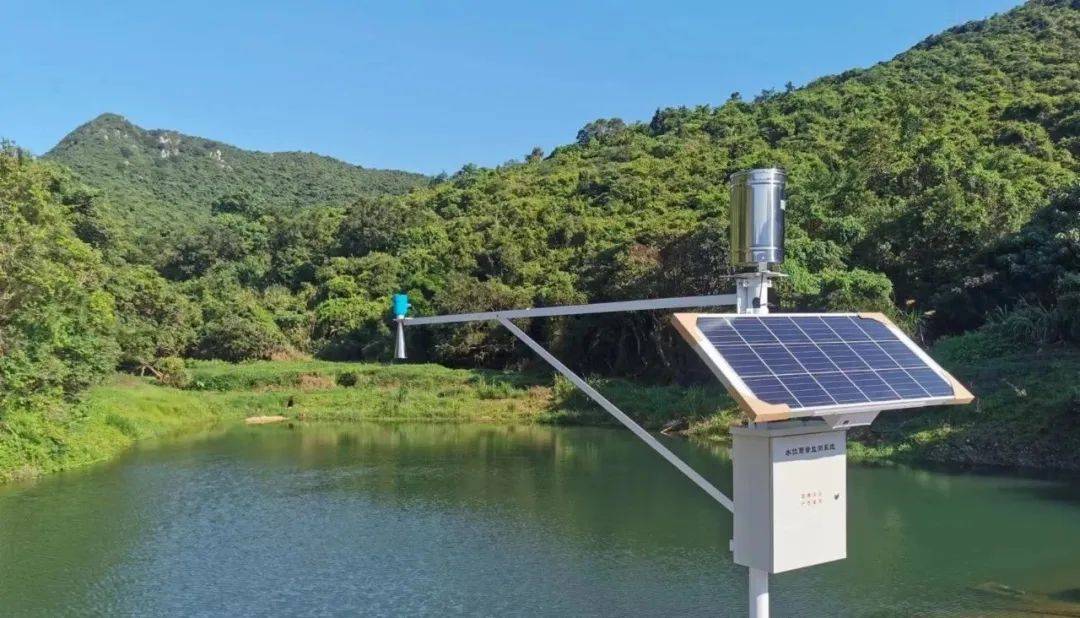
Reservoir water and rainfall monitoring supports resource accounting when level, storage, rainfall and discharge retain their meanings. Select suitable instruments, preserve reference information and use the correct capacity relationship. Keep measured data distinguishable from calculated volumes and operational decisions.
Prev:Soil Moisture Monitoring Instruments for Precision Agriculture
Next:PV Weather Station for Power Forecasting: Define Inputs and Validation
Related recommendations
Sensors & Weather Stations Catalog
 Agriculture Sensors and Weather Stations Catalog-NiuBoL.pdf
Weather Stations Catalog-NiuBoL.pdf
Agriculture Sensors Catalog-NiuBoL.pdf
Water Quality Sensor Catalog-NiuBoL.pdf
Related products
 Combined air temperature and relative humidity sensor
 TDR Soil Moisture & Temperature Sensor for irrigation| RS485 |4-20mA| NBL-S-THR
 Soil pH sensor RS485 soil Testing instrument soil ph meter for agriculture |NBL-S-PH
 Wind Speed sensor Output Modbus/RS485/Analog/0-5V/4-20mA
 Tipping bucket rain gauge for weather monitoring auto rainfall sensor RS485/Outdoor/stainless steel
 Pyranometer Solar Radiation Sensor 4-20mA/RS485


Screenshot, WhatsApp to identify the QR code
WhatsApp number:+8615367865107
(Click on WhatsApp to copy and add friends)

