





— Blogs —
—Products—
 Consumer hotline +8618073152920
WhatsApp:+8615367865107
Address:Room 102, District D, Houhu Industrial Park, Yuelu District, Changsha City, Hunan Province, China
Product knowledge
Time:2026-01-21 09:33:11 Popularity:855
Quick Answer: A submersible level transmitter measures liquid pressure at an immersed probe and converts it into depth. Select the probe arrangement, pressure range, liquid compatibility and output separately. A split display does not change the hydrostatic principle, and an IP68 water probe is not automatically suitable for a pressurized vessel or hot chemical liquid.
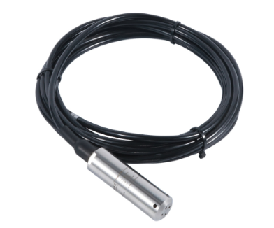
For an open tank, well or reservoir, hydrostatic pressure is the liquid density multiplied by gravitational acceleration and depth above the sensing diaphragm: P = rho x g x h. The measurement is contact-based. The probe, inlet, seals and submerged cable are exposed to the liquid; describing this arrangement as non-contact would lead to the wrong material and maintenance decisions.
The useful quantity may be depth above the probe, elevation relative to a survey datum or tank contents. These are different outputs. If the probe datum is 100.40 m and measured depth is 2.35 m, water-surface elevation is 102.75 m. Tank volume needs a geometry or strapping relationship; a cylindrical horizontal tank does not hold equal additional volumes for equal level increments.
In a sealed vessel, gas pressure above the liquid also reaches the submerged diaphragm. An atmosphere-referenced probe cannot separate that pressure from liquid head. Consider a suitable differential-pressure arrangement or another process-rated technology rather than compensating the problem with an arbitrary zero adjustment.
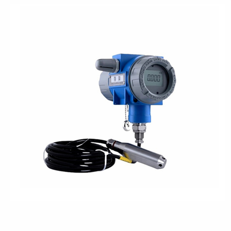
A compact submersible level transmitter sends its measurement directly to the receiving equipment. A split arrangement adds an accessible field housing or display above the liquid. This is useful when operators need a local indication, but the housing, connector and output must be specified independently of the submerged probe.
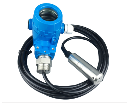
| Arrangement | Reason to choose it | Selection limit |
|---|---|---|
| Compact vented probe | Well, basin or reservoir with an existing PLC or data logger | Needs a dry atmospheric reference and a recoverable installation |
| Split-type transmitter | Local display, accessible connections or a separate field enclosure | Display availability, output and housing protection depend on the model |
| Temperature-specific assembly | Liquid exceeds the ordinary probe or cable temperature limit | Requires a separate temperature rating for all wetted components; not an assumed standard option |
| Alternative non-contact instrument | Probe immersion or recurring deposits are unacceptable | Above-liquid access, surface behaviour and mounting geometry still require assessment |
A separate display is not proof of hazardous-area approval. Likewise, a stainless-steel capillary or isolation diaphragm should not be inferred from a product-family photograph. When those features matter, identify the exact assembly and its temperature, pressure and material limits before comparing prices.
The following values apply to the NBL-L-WLPS RS485 configuration. They are not a combined specification for every split-type or current-output transmitter shown on this page.
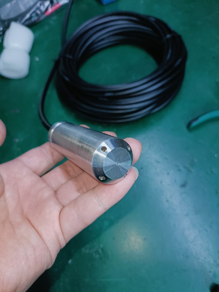
| Item | NBL-L-WLPS RS485 configuration |
|---|---|
| Measurement principle and range | Diffused-silicon piezoresistive hydrostatic measurement; range selected by ordered model suffix |
| Accuracy options | 0.5% FS default; 0.2% FS and 0.1% FS options |
| Long-term stability | +/-0.2% FS/year |
| Supply | 10-30 VDC; typical 24 VDC |
| Maximum power consumption | 0.2 W for this transmitter configuration |
| Output and protocol | RS485 / Modbus RTU |
| Serial configuration | Default 4800 bit/s, 8 data bits, no parity, 1 stop bit; address default 1 |
| Sampling time | No more than 1 second |
| Transmitter circuit temperature | -20 to 80 degrees C; long-term liquid measurement at no more than 60 degrees C |
| Probe protection and diameter | IP68; 26.8 mm outside diameter |
| Materials and cable | Stainless-steel probe with vented cable; specify exact wetted alloy, seals, jacket material and cable length for the liquid |
Range affects an FS-based accuracy allowance. At 0.5% FS, a 5 m range corresponds to 25 mm, whereas a 20 m range corresponds to 100 mm. These calculations explain the scale of the stated accuracy, not complete installed uncertainty. Density, reference elevation, temperature and installation effects remain relevant. Choose enough capacity for maximum head without buying an unnecessarily large span.
A water-scaled probe immersed 1.00 m in a liquid with density 1300 kg/m3 experiences approximately the pressure of 1.30 m of water, assuming water density of 1000 kg/m3. A water-equivalent reading therefore overstates physical depth by 0.30 m unless the density basis is corrected. State whether density is fixed or changes with concentration and temperature.
For atmospheric compensation, the vented cable must admit ambient pressure to the reference side without admitting water. Do not seal the vent inside an airtight potting compound or crush it with a cable gland. A trapped reference can turn weather changes into apparent level changes: an uncompensated 10 hPa pressure change is equivalent to about 102 mm of water head at 1000 kg/m3 and g = 9.81 m/s2.

Provide a dry termination with a protected, downward-facing vent outlet and an appropriate moisture-management arrangement. Leave service access to inspect it. Cable length must reach that dry location, not merely the water surface, and field splicing must preserve both the electrical seal and atmospheric path.
For wastewater, seawater or a chemical mixture, confirm compatibility against actual concentration and temperature. Stainless steel is not a universal corrosion solution, and an isolation diaphragm does not make the cable jacket chemically resistant. Deposits blocking the pressure inlet can introduce slow or stuck readings even when communication remains normal.
Connect the probe to a compatible PLC, RTU or data logger; use a gateway if remote networking is required. The probe's Modbus RTU interface does not itself provide cellular upload. Configure one device at a time before joining a shared bus, since duplicate default addresses prevent reliable identification.
For this configuration, register 0x0002 identifies the unit, 0x0003 the decimal places and 0x0004 the measured value. Function 03 can read these values. A raw value of 101 with three decimal places and metres as the unit means 0.101 m. A dashboard displaying 101 m has a decoding problem, not a hundred-metre rise in the tank.
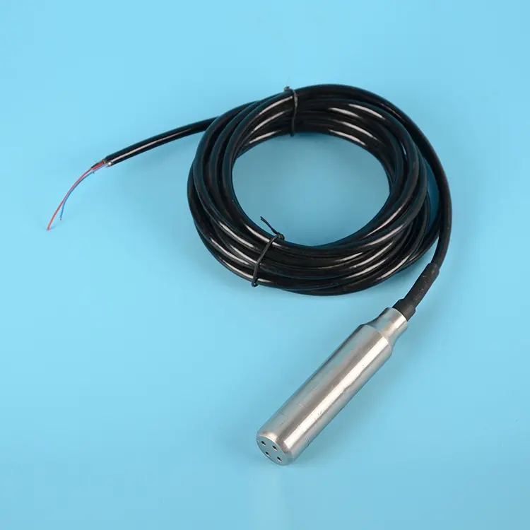
Store the unit and decimal interpretation with the measurement configuration. Avoid changing span, offset or scaling just to make a display resemble a dip reading. First confirm that both readings reference the same elevation and time. Check the supplied lead labels: different cable versions can use different colours for power negative and RS485 B.
A dedicated 4-20 mA model can suit an existing analogue input, but its loop power, load allowance and scaling need their own checks. Do not apply a current-meter adjustment procedure to the RS485 probe or assume both outputs are simultaneously available.
In a groundwater well, confirm bore clearance, lowest expected water level and a recoverable suspension point. Record probe elevation so later cable movement does not look like aquifer change. In a pump sump, locate away from direct inlet jets and pump suction, and use suitable protection against movement without restricting liquid access to the pressure inlet.
For an irrigation reservoir, allow for sediment growth and changing bank access. The probe should remain below minimum operating water level but clear of deposits. A stilling arrangement may reduce turbulence, provided it communicates freely with the monitored water and does not trap a different level.
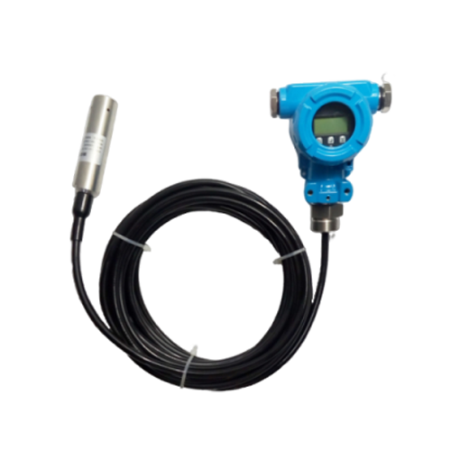
Industrial tanks add temperature, cleaning chemicals and process-pressure concerns. Check the most severe cleaning condition as well as normal service. If the system needs a local display, compare split-type level transmitter options separately; do not transfer the WLPS electrical table to them.
Inspect the vent, sealing, cable support and unobstructed inlet first. Then compare stable levels at several independently known points across the operating interval. Keep the reference instrument, elevation, liquid temperature and settling conditions consistent. A simulated PLC input verifies display scaling; it does not test the immersed diaphragm.
If the probe is raised during maintenance, restore its elevation or revise the datum before returning the channel to service. Check loss of communication and power separately from a legitimate low level. Preserve local pump protection independently of a remote dashboard and select alarm delays from the process, not a generic sensor recommendation.
Use the fault pattern to narrow the investigation. A steady level offset after retrieval suggests a changed probe elevation or zero setting. A value that changes with cabinet heating or weather while an independent level stays steady suggests a reference-path problem. A slow response after a real level change calls for an inlet and deposit inspection. Readings that become unstable only while a pump runs call for checks of local turbulence, power at the probe and interference. Compare the raw register with the display before changing any calibration value.

Not automatically. An atmosphere-referenced probe also senses pressure above the liquid. Specify vessel pressure and its variation so a suitable differential or other process-rated arrangement can be selected.
No. Include maximum operating head and required margin, then assess the FS-based error in millimetres. An oversized span can sacrifice useful level discrimination without improving installation suitability.
Only with a method that maintains sealing, conductor integrity and the vented reference. Order the required cable length where possible; an ordinary electrical splice is not enough for an immersed vented cable.
No. Ingress protection does not establish chemical compatibility or hazardous-area approval. Those requirements need separate material and certification checks for the complete supplied assembly.
Set the interval from application tolerance, deposit rate and recorded reference checks. Clean and inspect the inlet and vent before attributing a discrepancy to electronic drift; no single annual interval suits every liquid.
Give liquid composition and density, normal and maximum temperature, maximum head, required accuracy in mm, output, cable length and display requirements. Include access and installation details so the quoted probe is usable, not merely within the requested range.
A submersible level transmitter is appropriate when immersion is acceptable and hydrostatic pressure can be converted into the required level reference. Compare models by range-related error, vent arrangement, liquid compatibility and receiving interface. Send those conditions to NiuBoL for a probe and cable configuration matched to the installation.
Prev:Level Sensor Output Selection: Switch, 4-20 mA or RS485?
Next:Submersible Level Transmitter Accuracy: Full Scale and Field Error
Related recommendations
Sensors & Weather Stations Catalog
 Agriculture Sensors and Weather Stations Catalog-NiuBoL.pdf
Weather Stations Catalog-NiuBoL.pdf
Agriculture Sensors Catalog-NiuBoL.pdf
Water Quality Sensor Catalog-NiuBoL.pdf
Related products
 Combined air temperature and relative humidity sensor
 TDR Soil Moisture & Temperature Sensor for irrigation| RS485 |4-20mA| NBL-S-THR
 Soil pH sensor RS485 soil Testing instrument soil ph meter for agriculture |NBL-S-PH
 Wind Speed sensor Output Modbus/RS485/Analog/0-5V/4-20mA
 Tipping bucket rain gauge for weather monitoring auto rainfall sensor RS485/Outdoor/stainless steel
 Pyranometer Solar Radiation Sensor 4-20mA/RS485


Screenshot, WhatsApp to identify the QR code
WhatsApp number:+8615367865107
(Click on WhatsApp to copy and add friends)

