





— Blogs —
—Products—
 Consumer hotline +8618073152920
WhatsApp:+8615367865107
Address:Room 102, District D, Houhu Industrial Park, Yuelu District, Changsha City, Hunan Province, China
Product knowledge
Time:2026-09-11 15:00:00 Popularity:190
Quick Answer: A groundwater quality monitoring station with pumped sampling must record the sampling cycle as well as the sensor values. Separate startup, purging, stabilization, accepted measurement and cleaning states. Only publish a representative, valid observation as groundwater data; idle-chamber readings, air bubbles and retained values after a failed cycle need separate status flags.
A scheduled pump start does not establish that fresh groundwater has reached the instruments. Water may remain in tubing or a flow chamber between cycles. Its temperature and dissolved-gas condition can change, and sediment can settle. The station therefore needs a way to distinguish an instrument reading from an accepted groundwater observation.
This article concerns a pumped wellhead measurement arrangement. For deciding which parameters and downhole geometry fit an investigation, use the separate groundwater monitoring parameters guide. The automatic sequence still has to follow the sampling method approved for the well and investigation.
Confirm the intake position, well construction and whether water passes through treatment, storage or aeration before reaching the station. A cabinet installed near a well does not prove that its sample represents untreated aquifer water. Identify the complete wetted route in the station drawing.
| Cycle state | Meaning for the data record |
|---|---|
| Idle | Chamber values may be available, but are not automatically new groundwater observations |
| Startup and purge | Record flow and well response; mark readings as transitional |
| Stabilization | Evaluate the agreed field criteria and required sensor response time |
| Accepted measurement | Store valid parameter values with cycle identity and observation time |
| Cleaning or calibration | Keep maintenance values distinct from environmental results |
| Fault or timeout | Publish a diagnostic; do not replace a failed result with zero or an old value |
Set maximum run times and the response to failed stabilization in the control specification. Do not let a low-yield well be pumped indefinitely merely because an algorithm is waiting for a stable trace. An incomplete cycle should remain visible as incomplete, with its cause and any usable intermediate observations.
Keep the sensor timestamp, cycle start and accepted observation time distinct. If the logger uploads once per hour, it should not overwrite the actual time at which the groundwater observation was accepted. This distinction becomes important when comparing the station with a field sample or a pumping event.
As an illustration, 100 m of tubing with a 6 mm internal diameter contains about 2.83 L. At 0.2 L/min, nominal transit time is about 14.1 minutes, before adding chamber volume or allowing for mixing. This calculation describes transport volume only; it is not a universal purge time or a claim that the aquifer is represented after one tubing volume.
Record actual flow rather than inferring it from pump power. Restriction, changing head and filter condition can alter delivery. Compare the achieved flow with the approved sampling procedure and the well's response. If flow is missing, an apparently stable chamber trace may simply describe stagnant water.
For dissolved oxygen, exclude air ingress and bubbles from the sample route as required by the measurement method. Avoid unnecessary warming and open-container exposure. USGS guidance on multiparameter field instruments discusses flow-through arrangements and protection of withdrawn groundwater from temperature changes.
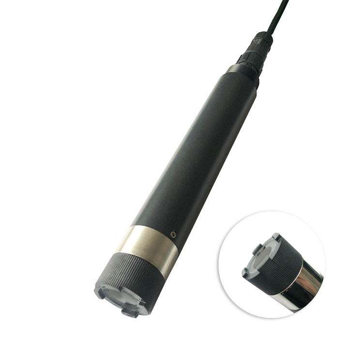
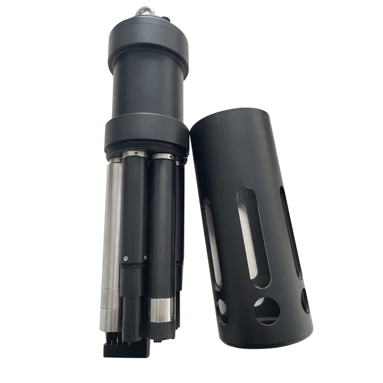
The NiuBoL NBL-WQ-MPS-5A is one possible multi-parameter sensor assembly. Verify the selected channels and their required mounting conditions. The sensor does not supply the well pump, flow chamber, valves or sampling-cycle logic.
| Selected assembly item | NBL-WQ-MPS-5A information |
|---|---|
| Optional pH channel | 0-14 pH; specified accuracy +/-0.1 pH; resolution 0.01 pH |
| Optional dissolved oxygen channel | 0-20 mg/L; confirm accuracy and compensation for the selected DO element |
| Optional EC channels | 0-5000 uS/cm or 0-200 mS/cm configurations; select the required range |
| Temperature channel | 0-50 deg C; resolution 0.1 deg C; confirm accuracy for the ordered assembly |
| Supply and consumption | 12 V DC +/-5%; 5 W at 12 V |
| Output and cleaning | RS485 Modbus RTU; automatic cleaning arrangement |
| Cable and deployment limits | Standard cable 5 m; confirm sheath, connector, pressure and ingress limits for the assembled installation |
Allow space for water exchange and the cleaning mechanism. Do not force a large assembly into a chamber that creates trapped air or stagnant pockets. The individual pH probe below illustrates a separate configuration; its maintenance and replacement arrangement differs from an integrated package.
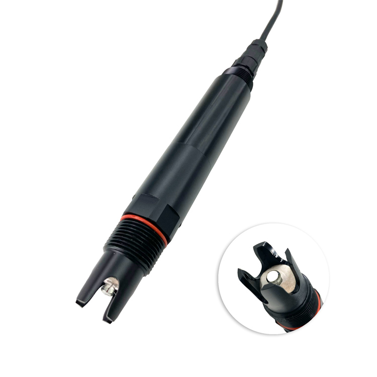
A pH electrode needs an appropriate storage and servicing method between operations. Confirm whether the chamber remains full, drains or is rinsed after a cycle. A general idle schedule must not leave an electrode in a condition unsuitable for the selected sensing element.
Temperature, EC, pH and DO can describe changing field conditions. Turbidity can help identify sediment disturbance or changing sample delivery. None of these channels alone establishes the absence of arsenic, nitrate, organic contaminants or microorganisms. Assign laboratory or dedicated methods to the actual substances of concern.
When turbidity changes during pumping, retain the flow, elapsed time and water-level information needed to interpret it. Do not filter a sample indiscriminately to make an optical reading stable: filtration can change the water fraction being investigated. The approved method determines whether and how conditioning is appropriate.
Implement each sensor's actual register map and units in the local RTU or data logger. Give separate probes unique addresses and confirm their communication settings individually. A label saying RS485 Modbus RTU does not guarantee the same register structure or measurement timing across models.
The cycle controller should know whether the pump ran, water arrived, required sensor channels were valid and stabilization criteria were met. Where a channel fails independently, decide whether the other results may be accepted or whether the entire cycle must be rejected. Keep that rule consistent with the investigation method.
Remote communication is a separate layer. Store the cycle locally during an uplink outage and transmit it later with its original identity and timestamps. A successful network upload must not turn a failed sampling cycle into an accepted environmental result.
A 5 W sensor powered continuously uses 120 Wh/day. For an illustrative intermittent station, a 30 W pump operating for 20 minutes over six daily cycles uses 60 Wh/day. Add the actual sensor duty, logger, modem and cleaning loads, then account for conversion losses and seasonal charging. These figures are examples, not a standard station configuration.
Power cycling may reduce energy consumption, but it can change stabilization needs and leave the chamber without valid current observations between cycles. State that sampling frequency explicitly. A station operating six accepted cycles per day does not provide an uninterrupted water-quality measurement simply because the platform stays online.
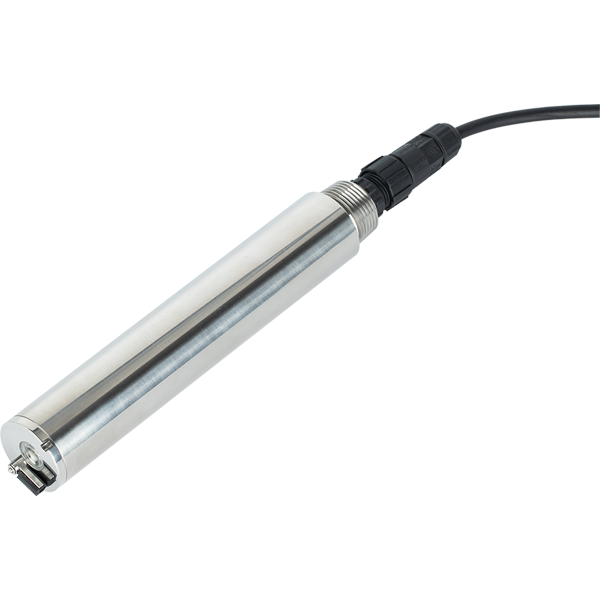
Plan access to remove probes, check tubing and service valves without introducing uncontrolled contamination into the well or sample route. The compact assembly below is another sensor option; select it on measured-channel and chamber requirements rather than assuming interchangeability with the first package.

Only if that period is justified by the approved method and validated installation. Tubing volume, flow, well response and sensor stabilization differ by site. A timer alone cannot demonstrate representative sampling.
Not without a valid measurement arrangement supporting that interpretation. Mark idle values separately from accepted sampling-cycle results and make their observation age visible.
No. Optical sensing does not prevent the water from exchanging gas or changing temperature before it reaches the probe. Assess the complete sample path, not only the sensing principle.
No. Pressure, depth, connectors, cable and retrieval limits need confirmation for the assembled configuration. This pumped-station design does not establish a downhole deployment rating.
Demonstrate the complete cycle, accepted-data criteria, no-flow fault, stabilization timeout and cleaning exclusion. Compare accepted observations using the specified reference method, and verify recovery after an uplink interruption.
Provide the well construction, intake position, tubing route, required parameters and approved sampling frequency. Identify pump, chamber, valves, waste handling, power and laboratory interfaces separately from the sensor package.
An automatic groundwater station needs a defensible sampling cycle before it needs a larger parameter count. Preserve sampling states, flow conditions and original observation times so that accepted values can be distinguished from transitional or maintenance readings. NiuBoL can assess the sensor and logger configuration after the sample route, channel requirements and operating cycle are defined.
Prev:Smart Fertigation System: Control Architecture and Installation Guide
Next:Automatic Weather Monitoring Station Installation Steps and Acceptance
Related recommendations
Sensors & Weather Stations Catalog
 Agriculture Sensors and Weather Stations Catalog-NiuBoL.pdf
Weather Stations Catalog-NiuBoL.pdf
Agriculture Sensors Catalog-NiuBoL.pdf
Water Quality Sensor Catalog-NiuBoL.pdf
Related products
 Combined air temperature and relative humidity sensor
 TDR Soil Moisture & Temperature Sensor for irrigation| RS485 |4-20mA| NBL-S-THR
 Soil pH sensor RS485 soil Testing instrument soil ph meter for agriculture |NBL-S-PH
 Wind Speed sensor Output Modbus/RS485/Analog/0-5V/4-20mA
 Tipping bucket rain gauge for weather monitoring auto rainfall sensor RS485/Outdoor/stainless steel
 Pyranometer Solar Radiation Sensor 4-20mA/RS485


Screenshot, WhatsApp to identify the QR code
WhatsApp number:+8615367865107
(Click on WhatsApp to copy and add friends)

