

— Blogs —
—Products—
 Consumer hotline +8618073152920
 WhatsApp:+8615367865107
Address:Room 102, District D, Houhu Industrial Park, Yuelu District, Changsha City, Hunan Province, China
Product knowledge
Time:2026-09-08 14:00:00 Popularity:219
Commission the probes, telemetry and power on shore before launch, then verify sensor depth and live data after the mooring settles.
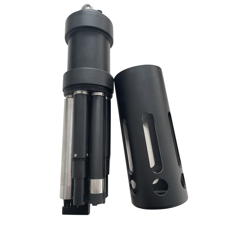
In the system, the probe is the field measurement layer; a controller, RTU, data logger or gateway handles display, alarms, storage and platform transmission. Before approving the water quality buoy installation model, trace the measurement point through cable protection, the logger input, communications, the database field and the alarm destination. For water quality buoy installation, a live number on a display by itself is only the first check. Across the water-quality monitoring system measurement chain, preserve engineering units, timestamps, Modbus addresses and device status.
| Decision field | Engineering requirement | Evidence for acceptance |
|---|---|---|
| Measurement purpose | State what action water quality buoy installation should support | Approved monitoring objective |
| Location for water quality buoy installation | Coordinates, depth or height, orientation and exposure | Drawing and installation photos |
| Data path | Sensor to logger, controller, gateway and platform | Current measurement with correct unit and timestamp |
| Maintenance for water quality buoy installation | Safe access and responsible person | Inspection and service record |
For sustained operation, describe water quality buoy installation as a measuring point with an operating purpose. The stated package boundary is more useful than an unsupported promise that the equipment is simply easy to install.
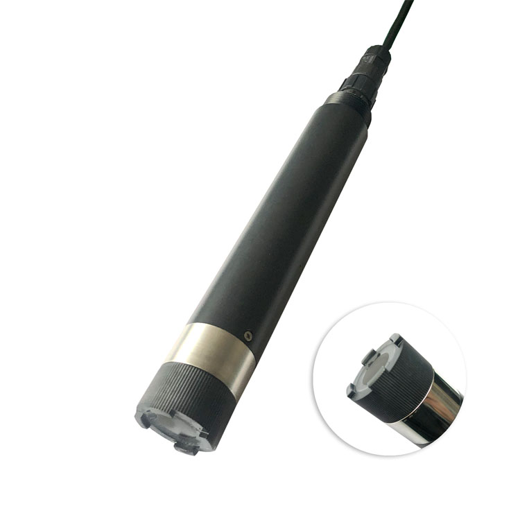
For water quality buoy installation, A key limitation is that defensible online data requires a representative sample, stable immersion or flow, cleaning access, calibration records and review of water-matrix effects. Write down the mounting geometry, first readings, comparison method, configuration and environmental condition. When water-quality buoy commissioning data shifts, compare the field condition with mounting, fouling, configuration and communication records before classifying it as a process event.
| RFQ item | Information to provide | Cost or risk controlled |
|---|---|---|
| Application | Purpose and site for water quality buoy installation | Prevents wrong product family |
| Measurement for water quality buoy installation | Normal, alarm and peak range; required interval | Avoids under-range or needless overspecification |
| Integration for water quality buoy installation | PLC/RTU/logger model, signal and protocol | Reduces panel rework |
| Mechanical for water quality buoy installation | Mounting, depth or height, cable route and material exposure | Defines accessories and serviceability |
| Supply scope for water quality buoy installation | Sensor only or complete station; documents and spares | Makes prices comparable |
| Commercial for water quality buoy installation | Quantity, destination, delivery target and packing | Supports a realistic quotation |
| Project role | Decision owned by that role | Deliverable before handover |
|---|---|---|
| Owner or project engineer | Define why water quality buoy installation is measured and the action threshold | Approved monitoring and acceptance plan |
| Distributor for water quality buoy installation | Convert the inquiry into a model, accessory and documentation scope | Traceable quotation and current datasheet |
| System integrator for water quality buoy installation | Confirm power, signal, addresses, scaling and platform tags | Wiring, register mapping and live data test |
| Engineering contractor for water quality buoy installation | Provide mounting, cable protection, grounding and safe access | As-built drawing and installation photos |
| Operator for water quality buoy installation | Carry out inspection, cleaning, checks and incident records | Maintenance log and abnormal-data response |
This division matters for water quality buoy installation because measurement faults often sit between contracts.
Before shipment, bench-test the selected water quality buoy installation with the intended power supply and host interface where practical.
For water quality buoy installation, do not close acceptance with a screenshot alone. Handover records for water-quality monitoring system should identify the serial number, installed position, cable and terminal, communication settings, initial comparison, platform tag and routine-inspection owner; include firmware or configuration references where available. Capturing this evidence while commissioning water-quality monitoring system is far easier than reconstructing it during a fault investigation.
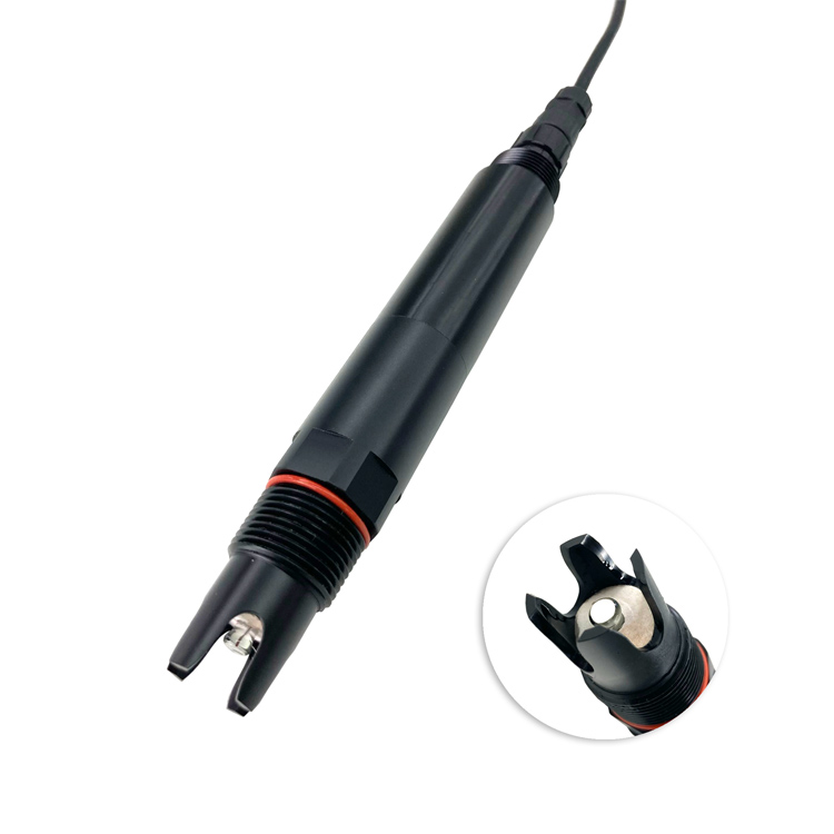
Referenced NiuBoL online probes use RS485 Modbus RTU, and selected model families may offer an analog output where an existing PLC requires it. Confirm any required 4-20 mA scaling, register map, device address and engineering unit before buoy commissioning.
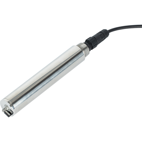
A1: Common parameters include temperature, pH, conductivity, dissolved oxygen, turbidity, chlorophyll and other project-specific indicators. Select them according to the water body and decision need.
A2: Choose a depth that represents the monitoring objective and remains submerged through expected level changes. Surface, thermocline and deeper-water studies may require different arrangements.
A3: Consider water-level range, current, wind, waves, vessel traffic, debris and access. The mooring must limit excessive movement without damaging the buoy or probes.
A4: Use suitable probe guards, wipers where available and a cleaning schedule based on water temperature and biological activity. Review drift between service visits.
A5: Solar panels and batteries are common. Size them for all probes, cleaning devices, logger, modem, navigation light and the required low-sun autonomy.
A6: 4G works where coverage is available; other radio or satellite options may suit remote waters. Local logging is essential when communication can be interrupted.
A7: Verify probe depth, mooring, sensor stabilization, reference checks, timestamps, upload, alarms, battery status and recovery after a controlled restart.
A8: Plan safe retrieval, cleaning, calibration, battery inspection and mooring checks. Service intervals should reflect fouling rate and the importance of continuous data.

A water-quality buoy must keep probes at a representative depth, protect them from collision and fouling, and provide dependable power, telemetry and service access. Mooring and maintenance are part of the measurement design.
Prev:How a PV Weather Station Supports Solar Plant Performance Analysis
Next:Rainfall and Soil Moisture Monitoring System Selection Strategy
Related recommendations
Sensors & Weather Stations Catalog
 Agriculture Sensors and Weather Stations Catalog-NiuBoL.pdf
Weather Stations Catalog-NiuBoL.pdf
Agriculture Sensors Catalog-NiuBoL.pdf
Water Quality Sensor Catalog-NiuBoL.pdf
Related products
 Combined air temperature and relative humidity sensor
 TDR Soil Moisture & Temperature Sensor for irrigation| RS485 |4-20mA| NBL-S-THR
 Soil pH sensor RS485 soil Testing instrument soil ph meter for agriculture |NBL-S-PH
 Wind Speed sensor Output Modbus/RS485/Analog/0-5V/4-20mA
 Tipping bucket rain gauge for weather monitoring auto rainfall sensor RS485/Outdoor/stainless steel
 Pyranometer Solar Radiation Sensor 4-20mA/RS485

Screenshot, WhatsApp to identify the QR code
WhatsApp number:+8615367865107
(Click on WhatsApp to copy and add friends)