





— Blogs —
—Products—
 Consumer hotline +8618073152920
WhatsApp:+8615367865107
Address:Room 102, District D, Houhu Industrial Park, Yuelu District, Changsha City, Hunan Province, China
Product knowledge
Time:2026-07-29 10:00:55 Popularity:301
Quick Answer: Online chlorine analyzer installation requires a representative sample, a controlled flow through the correct cell, and a defined connection to the controller. Establish whether the instrument reports HClO, free chlorine or another chlorine measurement before choosing its range or using its output for dosing. A sensor communicating successfully does not prove that the water reaching it still represents the process.
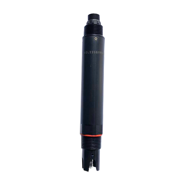
For a treatment skid or distribution monitoring point, the first decision is where the result is meant to apply. A measurement downstream of a contact tank answers a different question from one immediately beside a chemical injection point. Poor mixing can produce a locally high reading while other water follows a different path. Agree the treatment stage and sampling location before specifying the analyzer enclosure.
The sample route then becomes part of the measurement. Long tubing, low flow, trapped air, stagnant branches and deposits can delay or alter the sample. Keep the route practical to inspect and service. Select wetted materials for the water and disinfectant involved; do not assume that any available flexible tube is suitable for a low-level chlorine measurement.
Identify where the sample will discharge. The drain must accommodate normal flow without backing up into the cell. A bypass connected to a pressurized process needs an appropriate pressure-control arrangement, not simply a probe screwed into an unrestricted branch. Isolation should allow servicing without creating an uncontrolled release or interrupting an unrelated treatment function.
As an illustrative calculation, a 15 m tube with a 4 mm internal diameter contains about 0.188 L. At 40 L/h, the nominal displacement time is approximately 17 seconds. This calculation excludes the cell volume, mixing, any chlorine demand in the line and the sensor response. It is not the response time of a NiuBoL analyzer.
Increasing flow to reduce that delay is only acceptable within the cell and sensor limits. A responsive dashboard cannot remove a physical sample delay. For a dosing application, assess the complete process delay with the control engineer rather than tuning the controller from the network refresh interval.
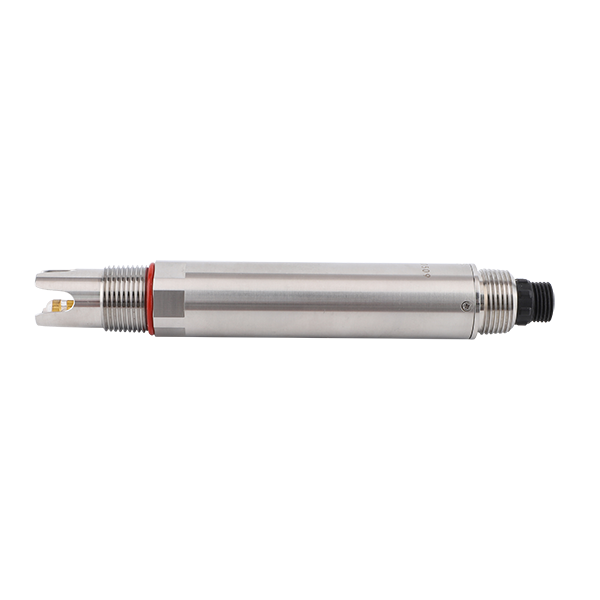
Residual chlorine is not one interchangeable output. HClO is the hypochlorous-acid fraction; a free-chlorine result and a total-chlorine result have different meanings. Water pH influences the balance between hypochlorous acid and hypochlorite. Therefore, an HClO reading must not be relabeled as a different chlorine result merely because the display uses mg/L.
NiuBoL offers different chlorine sensor constructions. The following table describes the NBL-WQ-CL constant-voltage option, not every chlorine probe pictured on this page. Match the ordered model, firmware and flow cell to the application. Compare individual product constructions before assigning one model's range, materials or pressure limits to another.
| NBL-WQ-CL characteristic | Specified value | Installation implication |
|---|---|---|
| Measurement | Constant-voltage method; 0-2.000 mg/L HClO | Check that HClO is the required result and that normal excursions remain within range. |
| Resolution and accuracy | 0.001 mg/L; accuracy stated as +/-5% or +/-0.05 mg/L | Confirm the applicable accuracy interpretation and acceptance method; display resolution is not accuracy. |
| Sample conditions | 5-50 degrees C; medium pH 4-9; pressure below 0.1 MPa | Condition the bypass before the cell; a pressure-rated main pipe does not establish probe suitability. |
| Cell flow | 30-60 L/h through the matching circulation cell | Measure and stabilize actual flow, rather than judging it from a valve position. |
| Supply and consumption | 12-24 V DC +/-10%; 0.2 W at 12 V | Budget the controller and accessories separately. |
| Output | RS485, Modbus RTU | Verify address, serial settings, register definitions and engineering units. |
| Construction | POM and PTFE; IP68 | Check chemical compatibility and protect cable terminations independently. |
| Temperature handling and cable | Pt1000 automatic temperature compensation; cable construction and length to be specified | Temperature compensation does not establish automatic conversion to total chlorine or a suitable field joint. |
If the required process result is free chlorine, ask how the proposed instrument obtains that result and what pH information it requires. If combined chlorine is important, specify that requirement explicitly. Comparing unlike chlorine measurements against the same numeric alarm limit can create a control error even when both instruments are functioning.
A practical assembly normally includes an isolation point, suitable pressure and flow control, the matched flow cell, accessible sensors and a defined outlet. Any strainer or conditioning component needs a reason: it may reduce blockage, but it also adds volume and a maintenance task. Check whether its materials or retained contamination can affect the chlorine result.
Mount the cell in the intended orientation and locate the measuring section as required by its construction. For the NBL-WQ-CL arrangement, stable flow near the inlet is important. Do not direct an uncontrolled jet at the electrode or allow bubbles to remain around its measuring surface. Provide enough access to remove the electrode without pulling against the cable.
After installation, inspect for leaks and establish flow with the sensor in its normal operating condition. Record the measured flow, sample temperature and pressure at the analyzer. Then observe whether these conditions remain stable when the process demand changes. A reading that moves with bypass pressure deserves a hydraulic check before a calibration adjustment.
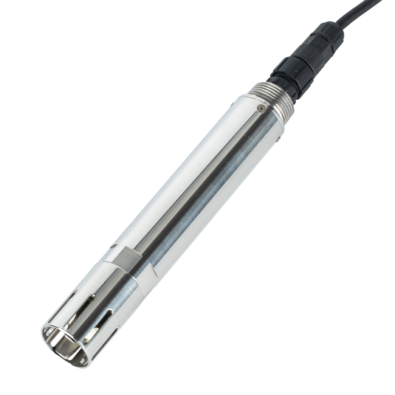
The NBL-WQ-CL sensor provides an RS485 Modbus RTU connection. Confirm polarity from the delivered wiring identification, use the correct supply, and configure each bus device with a unique address. Check termination and grounding for the installed network. RS485 alone does not establish compatible registers, units or fault handling.
A PLC or RTU must distinguish a valid low chlorine reading from a timeout, stale value or sensor fault. Test the data path with the actual device and retain both the engineering value and its validity. If a local analyzer controller provides 4-20 mA or relay outputs, verify that those functions are included in the ordered controller; they are not implied by the sensor's RS485 specification.
For an analog controller output, check the full measurement-to-current mapping and the configured fault behavior at the receiving input. For a digital connection, compare the local display and PLC value during a controlled test. Do not use a simulated current alone to claim that the water measurement has been calibrated.
A monitoring installation may use an alarm to prompt investigation. Automatic dosing also needs limits, loss-of-sample handling, suitable interlocks and a safe response to invalid measurements. A low reading caused by stopped sample flow must not automatically become an unrestricted command to add disinfectant. Control responsibility belongs in the process design.
For recurring disagreement, preserve the paired readings and operating conditions. A calibration change made during unstable flow can conceal the underlying problem and create a new error once normal flow returns. Cleaning and calibration intervals should follow actual fouling and drift, not a universal calendar copied from another water system.
For a quotation, send NiuBoL the water application, required chlorine result, expected range, pH and temperature, sample pressure, proposed location and PLC interface. Include the bypass route and whether the package needs a controller, cell, flow indication or outputs for existing automation. These details determine the assembly more directly than the phrase “online chlorine analyzer.”
Not by assuming that IP68 is a pipe-pressure rating. The NBL-WQ-CL option uses a matching circulation cell, flow of 30-60 L/h and pressure below 0.1 MPa. Review the bypass and pressure reduction for the actual process.
No. HClO is one component of free chlorine. Specify the intended result and establish how pH and the instrument's measurement method affect comparison with the plant's reference test.
No. A pH channel supplies additional information, but any conversion or compensation requires an implemented and appropriate algorithm. Verify the functions of the selected controller rather than inferring them from two connected probes.
The online sample may travel through tubing and a cell before reaching the electrode. Match sample locations and times, then consider transport, mixing and sensor response separately before diagnosing a communication problem.
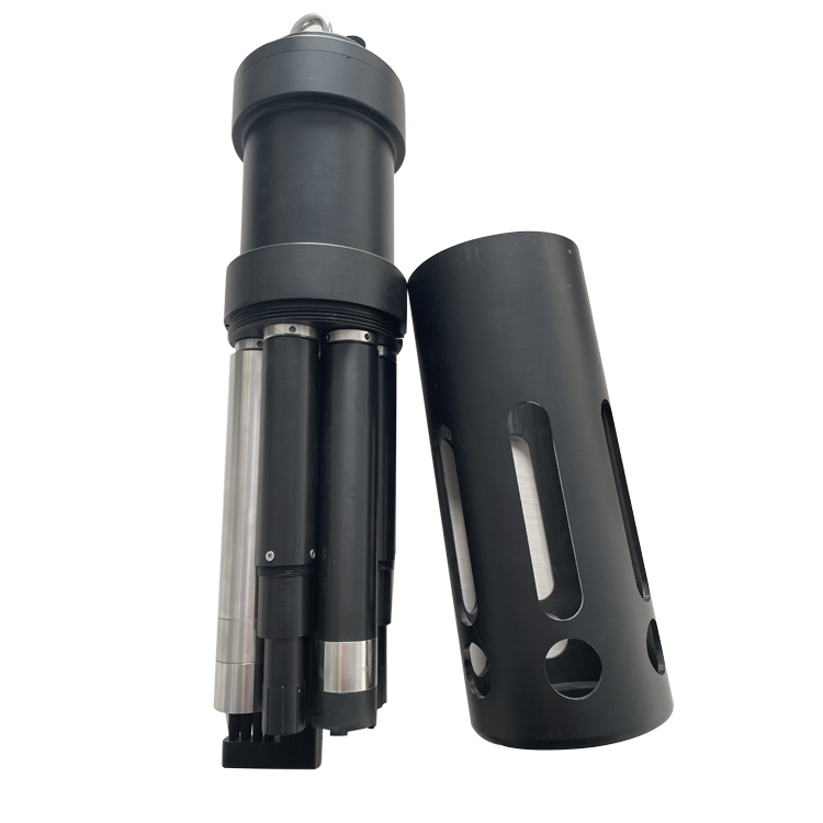
Only if its actual fitted channels and measurement method include the required chlorine result. The multiparameter probe pictured here illustrates a separate sensor construction; its appearance does not establish chlorine measurement capability.
Compare the exact sensor, controller, cell, sample conditioning, wiring and commissioning responsibilities. No fixed package price is stated here because those items and site conditions change the required assembly. Request a configuration-specific quotation.
Demonstrate a stable sample path and agreement with an appropriate reference under defined conditions, then prove the receiving controller handles invalid data correctly. A successful Modbus read is only the communications part of acceptance.
A usable chlorine monitoring point depends on the measurement definition and the water delivered to the electrode. Choose the correct chlorine method, respect the selected sensor's flow and pressure limits, and verify the controller handoff before enabling any automatic action. This prevents a well-connected instrument from reporting an unrepresentative sample.
Prev:Dissolved Oxygen Meter for Aquaculture: How to Prevent Low-DO Losses
Next:Aquaculture Water Quality Monitoring System: Sensors, Gateway and Alerts
Related recommendations
Sensors & Weather Stations Catalog
 Agriculture Sensors and Weather Stations Catalog-NiuBoL.pdf
Weather Stations Catalog-NiuBoL.pdf
Agriculture Sensors Catalog-NiuBoL.pdf
Water Quality Sensor Catalog-NiuBoL.pdf
Related products
 Combined air temperature and relative humidity sensor
 TDR Soil Moisture & Temperature Sensor for irrigation| RS485 |4-20mA| NBL-S-THR
 Soil pH sensor RS485 soil Testing instrument soil ph meter for agriculture |NBL-S-PH
 Wind Speed sensor Output Modbus/RS485/Analog/0-5V/4-20mA
 Tipping bucket rain gauge for weather monitoring auto rainfall sensor RS485/Outdoor/stainless steel
 Pyranometer Solar Radiation Sensor 4-20mA/RS485


Screenshot, WhatsApp to identify the QR code
WhatsApp number:+8615367865107
(Click on WhatsApp to copy and add friends)

