





— Blogs —
—Products—
 Consumer hotline +8618073152920
WhatsApp:+8615367865107
Address:Room 102, District D, Houhu Industrial Park, Yuelu District, Changsha City, Hunan Province, China
Product knowledge
Time:2026-09-08 12:00:00 Popularity:217
Quick Answer: A photovoltaic weather monitoring station should support performance analysis with irradiance, module temperature and relevant ambient weather, not simply reproduce a general meteorological package. Specify the measurement positions, sensor output versions, logger inputs and plant data connection together. A complete quotation must distinguish the instruments from mounting, power, communications and commissioning work.
A useful station schedule describes where each measurement comes from. Plane-of-array irradiance belongs in a plane representative of the modules; global horizontal irradiance requires a horizontal mounting plane. Module temperature is measured at a selected module back surface. Ambient temperature needs a ventilated radiation shield away from unusually hot structures. Combining those labels under one mast does not make their locations interchangeable.
For a fixed-tilt plant with a uniform array orientation, one arrangement may represent a defined block. A plant with east- and west-facing arrays, different tracker behavior or separated terrain needs a more detailed review. Decide which blocks must be evaluated independently before counting sensors. There is no universal station-per-megawatt rule that resolves orientation, shading and spatial weather differences.
Tracking and bifacial systems introduce additional choices. A tracker-representative irradiance sensor must follow the intended measurement plane. Rear-side irradiance requires a separate measurement design; a front-facing pyranometer cannot supply it. Select channels from the plant analysis requirements rather than adding every available weather parameter.
| Package element | What to specify | Common omission |
|---|---|---|
| Irradiance measurement | POA or horizontal plane, instrument type, calibration identification and signal version | A generic radiation channel without a matching bracket or calibrated logger scaling |
| Module and ambient temperature | Separate measuring positions, attachment method and shielded air sensor | Using ambient temperature as a substitute for module temperature |
| Wind and optional weather channels | Purpose, mounting height and required outputs | Assuming every channel shown in a product photograph is included |
| Data acquisition | Input types, channel count, sampling and recording intervals, storage and time synchronization | A logger with enough terminals but incompatible input electronics |
| Field installation | Mounts, cables, glands, enclosure, power and surge-protection interfaces | Unassigned foundations, cable pulling or tracker mounting work |
| Plant connection | Receiving system, protocol role, tag mapping and data-quality behavior | Assuming a cellular upload service includes plant SCADA integration |
Separate the base package from optional rain, humidity, pressure, soiling or rear-irradiance measurements. This allows comparable quotations without removing channels that the project actually needs. For example, rain helps explain wet periods and cleaning context, but a rainfall record is not a direct measurement of module soiling loss.
A compact ultrasonic weather sensor can collect selected ambient conditions through fewer mounts and cables. It is useful when the proposed position suits those measurements and the specified channel set is available. It does not replace a module-mounted temperature probe, and an integrated radiation option should not be assumed equivalent to a separately specified pyranometer.
Separate instruments allow different exposure positions and replacement of one channel without removing the whole assembly. The trade-off is more cabling, mounting and input configuration. Choose the arrangement by measurement purpose and service access, not by how many parameters fit inside one housing.
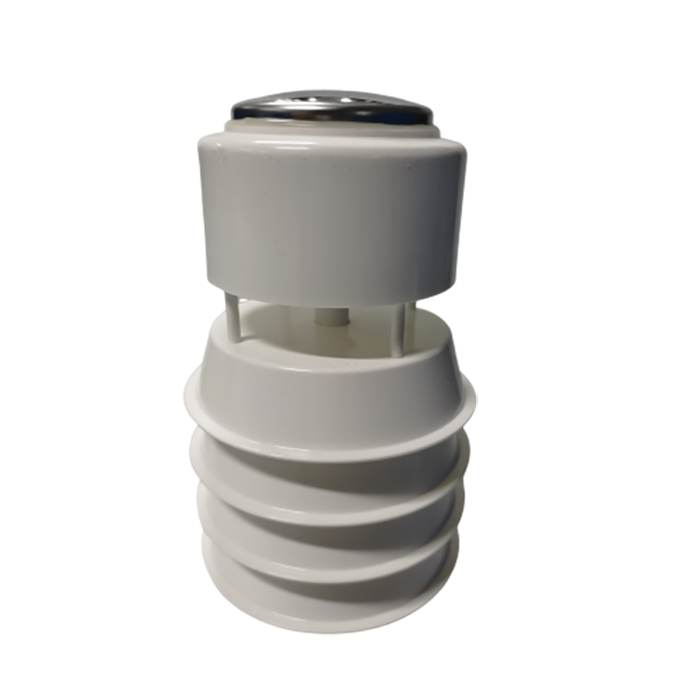
The following NiuBoL components illustrate choices within a photovoltaic weather monitoring station. Their specifications apply to the named components, not to a universal station package. Verify the ordered output and power variants before allocating logger inputs.
| Component | Relevant specifications | Connection decision |
|---|---|---|
| NBL-W-HPRS pyranometer | 0-2000 W/m2; spectral response 0.3-3 micrometers; response time up to 35 s to 99% | Choose the raw thermopile or conditioned output. RS485, voltage and current versions require different logger inputs. |
| NBL-W-PPT module temperature sensor | Range options -50 to 100 degrees C or -20 to 50 degrees C; accuracy +/-0.5 degrees C | Match the ordered range and signal. A short-range version may not cover the expected module temperature. |
| NBL-W-LBTH air temperature, humidity and pressure sensor | Temperature -40 to 80 degrees C, +/-0.5 degrees C; humidity 0-100% RH, +/-5% RH; pressure 10-1200 hPa, +/-1.5 hPa | 12-24 V DC. Select RS485 or the appropriate analog version and provide representative air exposure. |
| Wind speed and direction sensors | IP65; range, accuracy and signal depend on the selected model | Choose cup/vane or ultrasonic measurement and specify the wind-reference convention. |
A raw thermopile pyranometer produces a small voltage related to irradiance by its individual sensitivity. It needs a suitable low-level input and the correct calibration coefficient. Connecting it to an arbitrary 0-5 V input can sacrifice useful resolution. A conditioned 4-20 mA version instead needs an appropriate current input and defined scaling. Digital RS485 output avoids that analog conversion at the logger but still requires correct register interpretation.
Power options must be treated in the same way. The NBL-W-PPT has 5 V, 12 V and 24 V ordering options; this does not mean every delivered unit accepts all three. A terminal labeled RS485 says nothing about supply voltage. Include power polarity and signal identification in the wiring schedule for each supplied variant.
For an integrated weather assembly, establish which channels share a power source or communication address and what happens during servicing. If one unit is removed, the logger should flag the affected channels rather than carry forward apparently current values. A spare must have compatible firmware, scaling and mounting, not merely a similar exterior.
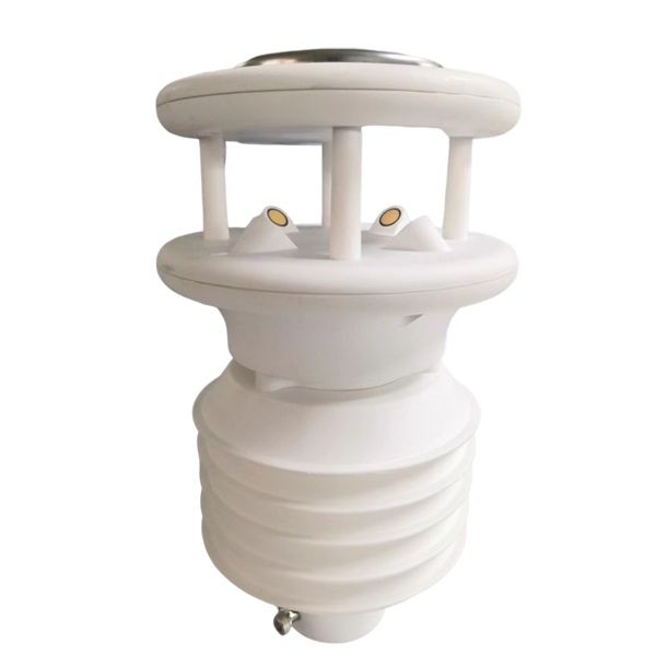
Field sensors feed a weather-station data logger, which records measurements and transfers them to the plant system. RS485 Modbus RTU may be used at the sensor side, while the receiving system could require Modbus TCP, an API or another specified interface. A logger with RS485 inputs does not automatically provide every upstream protocol.
Prepare a channel list containing the physical location, unit, register or analog range, recording interval and plant tag. Keep instantaneous samples distinct from averages, maxima and accumulated values. An upload every minute may contain a one-minute mean, a last sample or several timestamped samples; the data contract must say which. Wind gust reporting also needs a defined sampling and averaging method.
Specify clock synchronization and time-zone handling. Test whether stored records keep their acquisition timestamps after a network outage. Otherwise, delayed measurements may be aligned with the wrong inverter energy interval. Decide how missing readings, sensor faults and out-of-range values reach the plant historian; none should silently become zero irradiance.
Wind speed and direction help describe cooling conditions and weather exposure. A tracker safety function has different requirements, including sensor placement, response, redundancy and the controller's approved logic. Do not use a general weather-station upload path as the sole protective input unless the tracker and system designers have explicitly accepted it for that purpose.
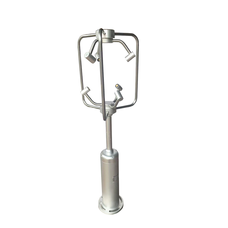
A three-dimensional ultrasonic anemometer is a separate option for investigations requiring vertical wind components or more detailed airflow data. Its inclusion should follow an actual study requirement. Ordinary solar performance reporting does not, by itself, justify replacing a suitable horizontal wind measurement with a 3D instrument.
Agree who provides the pyranometer mount, module probe attachment, mast foundation and cable routes. Keep the irradiance instrument clear of shadows from the mast, antennas and nearby rows over the relevant solar path. Check the final position after the whole station is assembled, not only when an isolated sensor is mounted.
Use a module-temperature attachment compatible with the module backsheet and supplier requirements. Provide strain relief without pulling on the sensing patch or obstructing module drainage. A detached probe can remain electrically connected while measuring the wrong temperature, so a plausible number is not proof of sound thermal contact.
For independent solar power, budget the logger, modem, sensors and any heaters at their relevant operating duty. A small solar panel pictured beside a station does not establish autonomy. Battery capacity, seasonal solar resource and allowable downtime must be resolved for the site. For plant-supplied power, clarify isolation, protective devices and what remains operational during a plant outage.
A comparison between adjacent irradiance instruments is useful only when their planes, cleanliness, time response and calibration are understood. Set acceptance tolerances around the actual instruments and test conditions rather than requiring every channel to match exactly. Include the calibration identifiers and completed tag list with the station records.

Some ambient channels may be reusable, but inspect the instruments and outputs first. A solar plant may need dedicated POA irradiance, module temperature and a plant data interface that the original station does not provide. Reuse suitable components instead of treating the existing parameter count as proof of suitability.
Not necessarily. Include each measurement when the plant specification or analysis requires it. GHI and POA describe different planes and are not interchangeable. Separate mounting and channel identification are needed when both are ordered.
No assumption should be made. A dashboard service and a plant interface are distinct deliverables. Specify the protocol, network route, tag mapping, credentials and responsibility for testing at the receiving system.
The instrument configuration, calibration requirements, number of measurement positions, logger interfaces, communications and installation accessories affect the quotation. Compare the same bill of materials and included services. A sensor-only price cannot be compared directly with an installed and commissioned station.
Provide the array layout and orientations, fixed or tracking design, required weather channels, receiving-system interface and available power. Add site conditions, cable distances and responsibilities for installation. NiuBoL can then discuss a component configuration and quotation tied to the plant rather than a generic station photograph.
A photovoltaic weather monitoring station is complete when its instruments, mounting and data connection match the plant's measurement plan. Select the sensor versions and logger together, distinguish optional measurements from required channels, and test the full path into the plant system. This prevents a delivered set of working sensors from becoming an unfinished integration project.
Prev:Tube Soil Moisture Monitor Installation: Borehole and Profile Checks
Next:How a PV Weather Station Supports Solar Plant Performance Analysis
Related recommendations
Sensors & Weather Stations Catalog
 Agriculture Sensors and Weather Stations Catalog-NiuBoL.pdf
Weather Stations Catalog-NiuBoL.pdf
Agriculture Sensors Catalog-NiuBoL.pdf
Water Quality Sensor Catalog-NiuBoL.pdf
Related products
Combined air temperature and relative humidity sensor TDR Soil Moisture & Temperature Sensor for irrigation| RS485 |4-20mA| NBL-S-THR
 Soil pH sensor RS485 soil Testing instrument soil ph meter for agriculture |NBL-S-PH
 Wind Speed sensor Output Modbus/RS485/Analog/0-5V/4-20mA
 Tipping bucket rain gauge for weather monitoring auto rainfall sensor RS485/Outdoor/stainless steel
 Pyranometer Solar Radiation Sensor 4-20mA/RS485


Screenshot, WhatsApp to identify the QR code
WhatsApp number:+8615367865107
(Click on WhatsApp to copy and add friends)

