





— Blogs —
—Products—
 Consumer hotline +8618073152920
WhatsApp:+8615367865107
Address:Room 102, District D, Houhu Industrial Park, Yuelu District, Changsha City, Hunan Province, China
Product knowledge
Time:2026-06-03 14:11:52 Popularity:362
Quick Answer: Sludge concentration meter installation must match the process stream, optical measuring space and maintenance access. A probe in an aeration plume, settled pocket or poorly exchanged bypass can produce an unrepresentative value even when communication works correctly. Identify whether the duty is basin MLSS, return sludge, waste sludge or effluent before fixing the bracket and concentration range.
MLSS describes suspended solids in mixed liquor. A return-sludge line and an aeration basin can both contain biological solids but have different concentration bands and operating behavior. A common g/L display does not make the measuring points interchangeable.
Write the actual stream, normal level range, expected solids concentration and purpose beside the sensor position. This helps prevent an installer from moving the probe to a more convenient point that measures different water. For terminology and process distinctions, see sludge concentration versus MLSS.
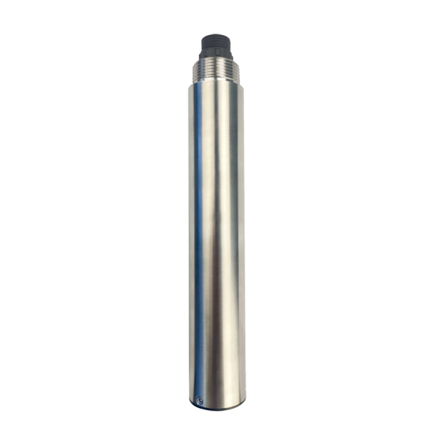
The first probe illustrated on this page is a TSS-4S configuration. It must not be assigned the range or automatic brush of the separate MLSS-408-S solely because the article concerns sludge monitoring.
| Characteristic | NBL-WQ-TSS-4S | NBL-WQ-MLSS-408-S |
|---|---|---|
| Range | 0-2000 mg/L | 0-20.000 g/L, equivalent to 0-20000 mg/L |
| Resolution | 0.1 mg/L | 0.001 g/L |
| Accuracy statement | +/-5%, dependent on sludge homogeneity; confirm percentage basis | +/-5% of reading, dependent on sludge homogeneity |
| Cleaning provision | Confirm supplied arrangement; do not assume an MLSS brush | Built-in mechanical cleaning brush |
| Water conditions | 0-50 degrees C; below 0.2 MPa | 0-60 degrees C; at or below 0.2 MPa |
| Supply / consumption | 12-24 V DC; 0.2 W at 12 V | 12-24 V DC; 0.2 W at 12 V excluding brush operation |
| Output | RS485 Modbus RTU; optional 4-20 mA | RS485 Modbus RTU; optional 4-20 mA |
| Construction / mounting | 316L; IP68; 3/4 NPT immersion; standard 5 m cable | 316L; IP68; 3/4 NPT immersion; standard 5 m cable |
The TSS-4S and MLSS-408-S are separate configurations. Neither should be selected outside its concentration band. Check cable jacket, connector, cleaner and wetted-material compatibility for the offered assembly rather than inferring them from its metal housing.
An optical sensor responds to its immediate measuring region. Avoid a stagnant recess where solids settle and a direct bubble plume where air repeatedly crosses the optics. The desired point still needs enough exchange to follow the bulk stream.
For the MLSS-408-S, maintain more than 5 cm from the side wall and more than 10 cm from the bottom. These are minimum optical clearances, not a recipe for selecting one universal immersion depth. Verify the actual clearances after the bracket is secured and under expected movement.
Before making the mount permanent, compare candidate positions during normal aeration and mixing transitions. Record whether the difference follows visible bubbles, local settling or a genuine process change. A calmer location is useful only if its solids remain representative.
Check the minimum water level as well as normal level. The optics must stay correctly submerged through the operating range. Raising a probe above deposits is not helpful if low water then leaves the sensing region exposed.
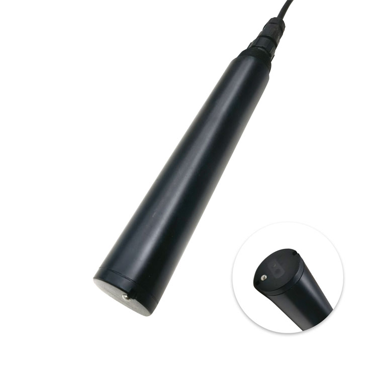
The second image is a separate optical probe example, not proof of the selected MLSS cleaning mechanism. Identify the fitted instrument at the bracket and in the maintenance record. A general sensor photograph should not replace a model-specific installation drawing.
Support the probe independently of its cable and provide a route for safe removal. Consider guardrails, lifting access, splashing and the ability to inspect the window without entering the tank. Cables need strain relief and protection from abrasion, moving machinery and debris.
For a self-cleaning unit, leave room for the brush to move and for authorized service. Do not locate a guard or mounting clamp where it obstructs the cleaning path. Isolate the mechanism as required before handling it; a remotely commanded brush can move while staff are working.
A pressure rating is not permission to unscrew a probe from a live line. If the duty requires pipe installation, obtain an engineered holder and isolation arrangement suited to that exact model. Do not substitute an improvised bypass simply to make an immersion probe fit.
Optical concentration is derived from light response; it is not a direct drying-and-weighing test. Particle properties and sludge uniformity affect the relationship with laboratory suspended-solids mass. Temperature compensation does not eliminate those effects.
Once the position is satisfactory, document the bracket reference and depth. Otherwise a future cleaning visit can unintentionally create a new measuring point. Record a cleaning event separately from a process event before deciding whether calibration needs adjustment.
Read RS485 Modbus RTU into the PLC, RTU or data logger using the delivered register definition. Verify decimal scaling and concentration units: 1 g/L equals 1000 mg/L. A factor-of-1000 error can remain plausible on a trend with an unsuitable axis label.
If a current output is ordered, confirm its full scale and compare the converted analog value with the digital result. Include brush operating demand in the supply design where applicable. A missing channel must be flagged as unavailable, not converted to zero sludge.
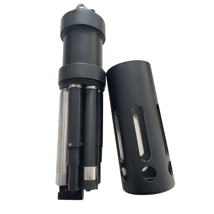
The multiparameter assembly below illustrates another instrument construction. Additional pH or DO channels can provide process context, but they cannot establish the dry-solids relationship for an optical MLSS channel.
No. Five g/L equals 5000 mg/L, outside that range. Select an appropriate concentration range and validate its optical response for the actual sludge.
Not if bubbles or local circulation make the measurement unrepresentative. Compare candidate positions while preserving adequate mixing and water exchange.
No. Brush movement, wear, fibers and persistent deposits still require inspection. Provide safe retrieval and maintenance space.
Not automatically. Avoid bottom deposits, preserve optical clearance and ensure that the point represents the intended stream. Confirm the pressure and low-level conditions as well.
Provide the stream name, normal and peak concentration, tank levels, aeration layout, temperature, pressure, cable route and access drawings. State the laboratory comparison method and required output.
Sludge concentration meter installation determines which solids the instrument actually observes. Match the range and model, verify optical clearance and representative mixing, then demonstrate the relationship with paired samples. A maintainable mounting point and correctly scaled receiving channel are more useful than an accessible but unrepresentative reading.
Prev:Aquaculture Pond pH Monitoring: Daily Cycles and Abnormal Readings
Next:pH Electrode Maintenance Intervals: Cleaning and Drift Checks
Related recommendations
Sensors & Weather Stations Catalog
 Agriculture Sensors and Weather Stations Catalog-NiuBoL.pdf
Weather Stations Catalog-NiuBoL.pdf
Agriculture Sensors Catalog-NiuBoL.pdf
Water Quality Sensor Catalog-NiuBoL.pdf
Related products
 Combined air temperature and relative humidity sensor
 TDR Soil Moisture & Temperature Sensor for irrigation| RS485 |4-20mA| NBL-S-THR
 Soil pH sensor RS485 soil Testing instrument soil ph meter for agriculture |NBL-S-PH
 Wind Speed sensor Output Modbus/RS485/Analog/0-5V/4-20mA
 Tipping bucket rain gauge for weather monitoring auto rainfall sensor RS485/Outdoor/stainless steel
 Pyranometer Solar Radiation Sensor 4-20mA/RS485


Screenshot, WhatsApp to identify the QR code
WhatsApp number:+8615367865107
(Click on WhatsApp to copy and add friends)

