

— Blogs —
—Products—
 Consumer hotline +8618073152920
WhatsApp:+8615367865107
Address:Room 102, District D, Houhu Industrial Park, Yuelu District, Changsha City, Hunan Province, China
Product knowledge
Time:2026-09-17 16:00:00 Popularity:207
A tap water online quality monitoring system for an existing pump room should establish what changes between incoming water, storage and the water delivered to the building. Select the disinfectant-residual method first, then add low-range turbidity and supporting channels where they answer a specific operating question. Include the sample-water connection, drainage and service arrangements in the design; an instrument cabinet alone does not define a working monitoring point.
In a retrofit, the useful question is often whether an abnormal reading originates in the incoming supply or develops within storage and distribution. A single outlet monitor can identify a change at that outlet, but it cannot attribute the cause. An incoming-water comparison point helps separate an upstream event from a tank or building-system issue.
Draw the actual water route before selecting instruments. Identify direct-supply branches, storage tanks, booster sets and pressure zones. A monitor on the common pump discharge may represent several downstream branches only while those branches receive the same water. It does not describe a stagnant remote outlet or an independently supplied zone.
Incoming and outgoing measurements are not necessarily measurements of the same parcel of water at the same moment. Tank level, turnover and demand influence the comparison. Retain those operating records when investigating a residual decrease. Simply subtracting simultaneous inlet and outlet values can misrepresent storage effects when the incoming water has recently changed.
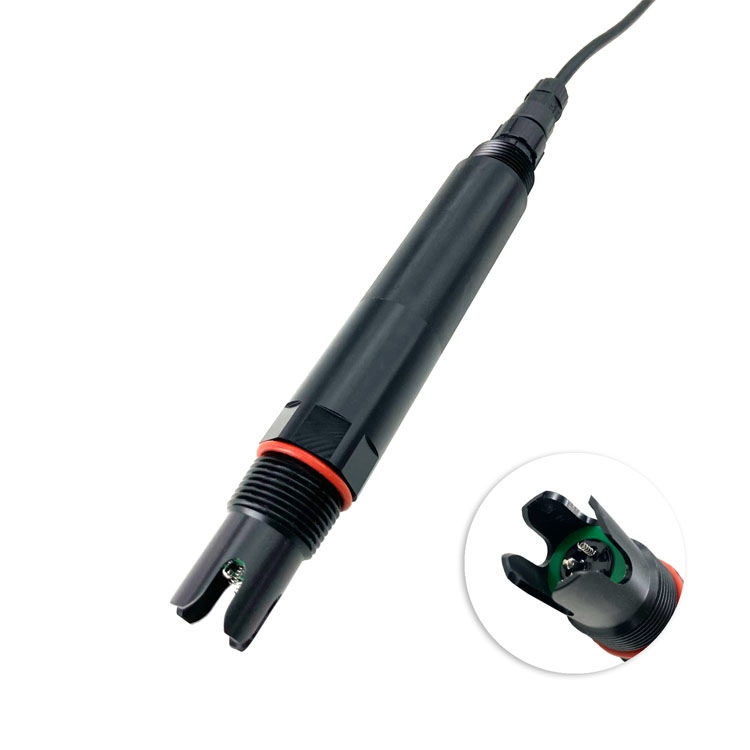
Keep analytical investigations separate from the routine pump-room package. An optical BOD sensor, shown below, may support a defined organic-load study after validation, but it does not identify pathogens or establish that tap water is acceptable for consumption. Its presence should follow a specific investigation, not an assumption that more parameters automatically create a safer supply.

| Pump-room question | Measurement to consider | Condition for useful interpretation |
|---|---|---|
| Has the specified disinfectant residual changed across storage? | Method-matched residual measurements at selected points | Identify the disinfectant and chlorine fraction; account for water residence and sample delay |
| Does a disturbance coincide with tank work or pump operation? | Low-range turbidity with event records | Rule out bubbles or sediment released from the sampling connection |
| Has the incoming supply or blend changed? | Conductivity and temperature, with pH where relevant | Compare like-for-like compensation settings and retain source-switch information |
| Is the measurement point itself unavailable? | Sample-flow indication, instrument status and data age | Display a fault rather than continuing to present an old value as current |
Turbidity and suspended-solids concentration are different quantities. The TSS probe below is intended for a mass-concentration monitoring task; it should not be substituted for a low-range turbidity instrument merely because both respond to particles. For clear tap water, specify the optical method and performance around the small changes of interest.
Online residual, pH, conductivity and turbidity are operational measurements, not a complete safety assessment. Retain the microbiological and chemical testing required for the supply. The EPA's online water-quality monitoring resources distinguish monitoring applications and the associated response arrangements. Do not label a general sensor package as a replacement for the applicable drinking-water testing program.

The NiuBoL NBL-WQ-CL is a constant-voltage sensor with a 0-2.000 mg/L HOCl measurement range. This is a specific analytical duty. Determine whether the supply uses free chlorine or chloramines and whether the project requires free, combined or total chlorine. A sensor responding to HOCl should not be accepted as a total-chlorine analyzer without evidence that it measures the required quantity.
For a free-chlorine application, agree the reporting basis and how pH affects the comparison. The sensor's pH operating range is not a statement that its response is independent of pH. If the water chemistry or expected residual falls outside the model's validated duty, select a different measurement arrangement instead of correcting the mismatch with a display label.
| NBL-WQ-CL requirement | Technical value | Retrofit implication |
|---|---|---|
| Range and resolution | 0-2.000 mg/L HOCl; 0.001 mg/L resolution | Check the measurand and normal/upset range before ordering |
| Accuracy | +/-5% or +/-0.05 mg/L | Agree the percentage basis and application of the error terms before acceptance |
| Sample flow | 30-60 L/h in the matched circulation cell | Provide a measurable, stable branch flow and an approved discharge route |
| Water conditions | 5-50 C; pH 4-9; pressure below 0.1 MPa | Check pressure changes over the booster operating cycle |
| Supply and power | 12-24 V DC +/-10%; 0.2 W at 12 V | Include other panel loads separately; inspect available power capacity |
| Interface | RS485, Modbus RTU | Confirm compatible inputs or a specified interface to the existing BMS |
| Construction | POM and PTFE; IP68 probe; approximately 6 mm cable outside diameter | Protect terminations and confirm cable length and jacket suitability |
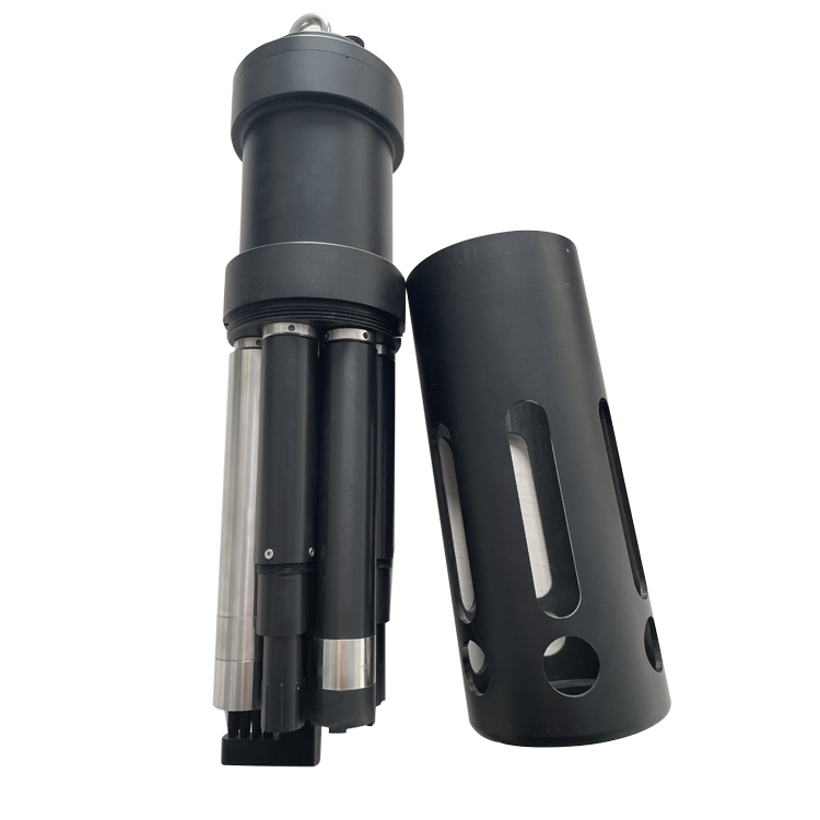
A multi-parameter assembly can reduce the number of separate installations when the required channels share the same water. However, the NBL-WQ-MPS-5A pictured below does not make a chlorine channel available simply because it combines other water-quality parameters. Its selected channels and performance must be assessed independently; the residual measurement may still need its own circulation cell.
A booster discharge can exceed the sensor's permitted pressure. Design pressure reduction and isolation for the actual operating envelope, then measure conditions at the cell while pumps start, stop and change duty. A partly closed hand valve may reduce flow without reliably limiting static pressure when the outlet is blocked.
For a drain-to-waste design, the CL branch at 30-60 L/h uses 720-1440 L per day if operated continuously. Two independent branches at that flow would use 1440-2880 L per day. These are calculated water volumes, not the water use of every monitoring station. Include additional branches and any bypass flow in the actual design calculation.
Do not reduce the flow below the instrument's required condition simply to meet a water-use target. Nor should sample water be returned to a potable tank through an improvised connection. Have the qualified water-system designer approve the discharge or return arrangement and any backflow protection required locally. Water use can change whether the proposed installation is practical.
A low-range turbidity cell may need a different flow from a chlorine cell. For example, the NBL-WQ-TSA-4 has a recommended drain flow below 300 mL/min, while the CL requires 0.5-1.0 L/min. Do not put them in one assumed series flow path. Use an engineered branch arrangement and check the condition of each measurement independently.
The technician needs to remove the electrode, catch or route draining water, compare a reference sample and inspect the cell without reaching across exposed electrical connections. Place valves and labels where they remain visible after the door opens. A cabinet that fits the wall but cannot be serviced safely is not ready for procurement.
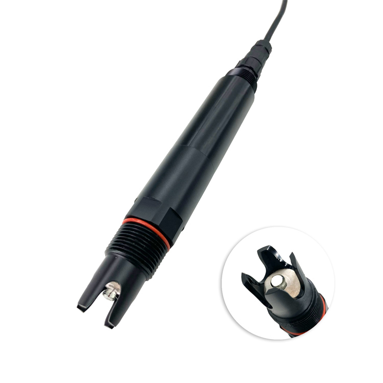
A separate pH channel can help interpret residual changes and water-chemistry shifts. The pH probe below should measure representative water under its own installation requirements. Record its calibration and the time of each reading so it provides useful context; a stale pH value can make an otherwise valid residual comparison difficult to interpret.
Only if the intended decision concerns the combined outlet and that point receives representative water. It cannot identify which separate tank caused a change. Where attribution matters, consider individual outlet measurements or a planned comparison program. If sample switching is used, test flushing and carryover before treating successive results as independent tank measurements.
Check the available physical interface and protocol, not just whether the BMS has spare points. An RS485 Modbus RTU input must use the sensor's register map and scaling. An analog-only controller needs a suitable ordered output or conversion device. Test value, unit and stale-data behavior before accepting the integration.
No. First establish that the result is valid and investigate the water path, chemistry and operating condition under the site's procedure. A monitoring retrofit does not authorize chemical treatment or define a dose. Any control function needs a separately engineered treatment strategy, permissions and safeguards appropriate to the supply.
Take a time-matched comparison sample at the measuring point, record flow and inspect for air or restrictions. Then test sample interruption deliberately and verify a fault indication. During normal pump cycling, observe pressure, flow and readings together. This shows whether an apparent water-quality event is associated with the sampling arrangement.
Identify the affected measurement point and mark the maintenance period in the data record. Follow the water-system operator's cleaning and return-to-service procedure. Do not use a short period of normal online readings as the sole acceptance of the cleaned tank; retain the checks required by that procedure.
Provide the tank and pump layout, supply disinfectant, desired measuring points, pressure range, drainage arrangement and BMS interface. Identify who supplies the sample plumbing and performs reference testing. Ask NiuBoL to price a configuration against those details, with any required controller and cell identified, rather than comparing an unspecified sensor package with a completed installation.
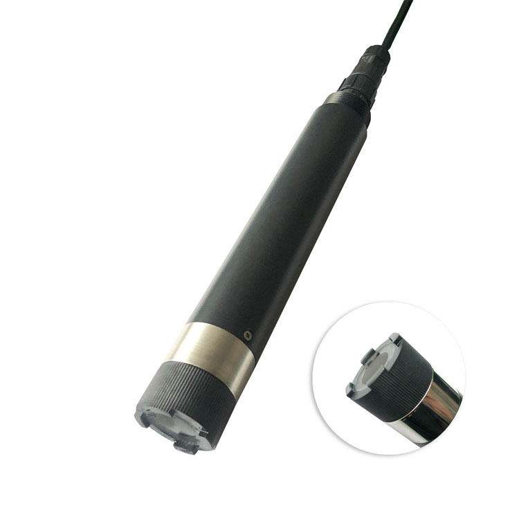
It is not a default substitute for residual-chlorine or microbiological testing. The optical DO sensor below may be relevant to a defined treatment or diagnostic study. Install it when the project has a clear oxygen-related question and a method for interpreting the result, rather than using it to imply general drinking-water safety.
A tap water online quality monitoring system retrofit should help operators distinguish supply changes from storage and distribution problems. Establish the measuring-point boundary, choose the correct residual method and verify the sample hydraulics through normal pump operation. A clear layout and operating requirement give NiuBoL the information needed to evaluate a usable sensor configuration without adding unnecessary channels.
Prev:Online Water Quality Monitoring System Structure from Sensor to Platform
Next:Tap Water Turbidity Monitor: Low-Range Acceptance Tests
Related recommendations
Sensors & Weather Stations Catalog
 Agriculture Sensors and Weather Stations Catalog-NiuBoL.pdf
Weather Stations Catalog-NiuBoL.pdf
Agriculture Sensors Catalog-NiuBoL.pdf
Water Quality Sensor Catalog-NiuBoL.pdf
Related products
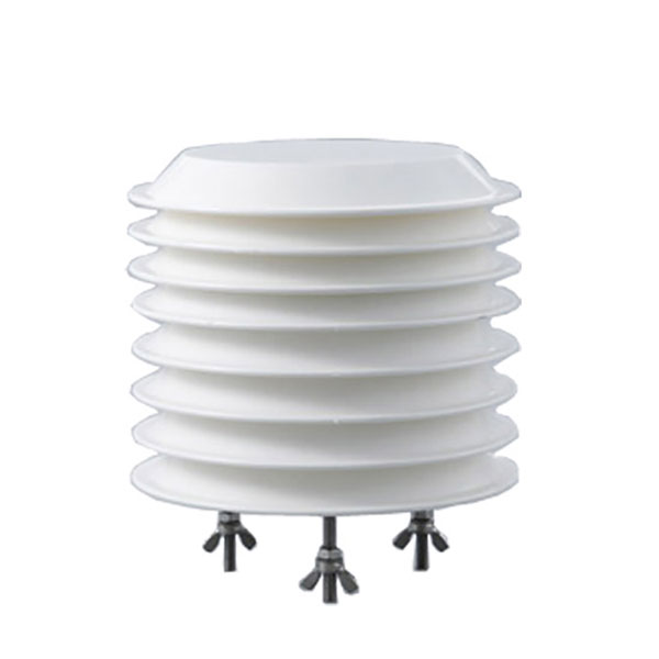 Combined air temperature and relative humidity sensor
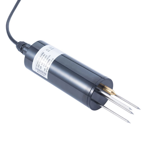 TDR Soil Moisture & Temperature Sensor for irrigation| RS485 |4-20mA| NBL-S-THR
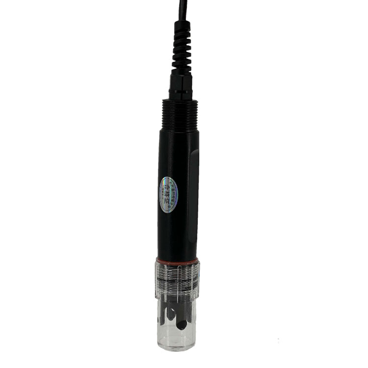 Soil pH sensor RS485 soil Testing instrument soil ph meter for agriculture |NBL-S-PH
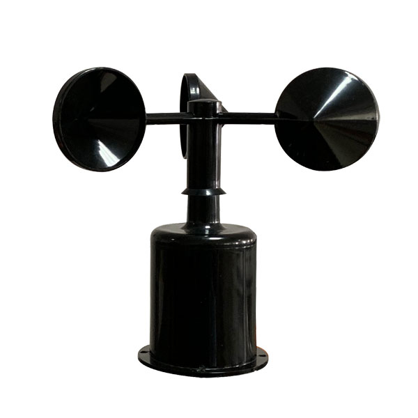 Wind Speed sensor Output Modbus/RS485/Analog/0-5V/4-20mA
 Tipping bucket rain gauge for weather monitoring auto rainfall sensor RS485/Outdoor/stainless steel
 Pyranometer Solar Radiation Sensor 4-20mA/RS485


Screenshot, WhatsApp to identify the QR code
WhatsApp number:+8615367865107
(Click on WhatsApp to copy and add friends)