





— Blogs —
—Products—
 Consumer hotline +8618073152920
WhatsApp:+8615367865107
Address:Room 102, District D, Houhu Industrial Park, Yuelu District, Changsha City, Hunan Province, China
Product knowledge
Time:2024-12-01 17:28:55 Popularity:2216
When an ultrasonic wind sensor reports missing, zero or unstable readings, first determine whether the instrument is communicating, whether the returned measurement is valid and whether its exposure has changed. A communication timeout is not calm wind. A constant value may be stale, while variable direction at very low speed can require different interpretation from a power or acoustic-path fault.

Record the model, output, supply and time the problem appeared. The NBL-W-21MUWS measures wind speed and direction. The NBL-W-51MUWS also measures air temperature, humidity and pressure. If only wind channels become abnormal while the other channels continue updating, that is a different diagnostic starting point from complete loss of response.

The NBL-W-61MUWS adds piezoelectric rainfall measurement. An abnormal rain channel does not by itself identify a fault in the ultrasonic wind measurement. Record whether rain values continue updating while the wind channels stop, and identify the affected quantities when contacting support.

For a configurable multi-parameter head, retain its actual channel list and firmware/configuration identity. Do not treat an uninstalled optional channel as a failed sensor. Save the existing settings and a short raw data sample before changing addresses, update intervals or software.

Ultrasonic wind measurement compares sound transit along opposing directions and derives wind components from the differences. Sound speed varies with atmospheric conditions; the measurement arrangement and processing account for propagation behaviour. This does not establish that every sensor has a separate ambient-temperature compensation channel or a Doppler measurement mode.
Obstruction, deposits, water or ice on the relevant surfaces can warrant inspection, especially when symptoms correlate with weather or recent work. Check the actual condition before assigning a cause. No moving cups means there are no cup bearings to service, but it does not make the acoustic paths or electronics immune to their environment.

| Example model | Supply and communication | Operating conditions |
|---|---|---|
| NBL-W-21MUWS | DC 12 V configuration; RS485 Modbus; 9600 baud; about 0.2 W | -40 to +70 C; IP65; 0-40 m/s speed range |
| NBL-W-51MUWS | DC 12-24 V; RS485 Modbus RTU; 9600 baud; about 0.3 W | -40 to +80 C; 0-95% RH; IP65 |
| NBL-W-61MUWS | DC 12-24 V; RS485 Modbus RTU; 9600 baud; about 0.35 W | -20 to +50 C; 0-95% RH; IP65 |
A measurement range is not necessarily the whole instrument's permitted operating environment. In particular, compare the complete head's operating temperature with site conditions rather than borrowing another model's range. IP65 is not an immersion, anti-icing or heater specification.

Check whether the receiver is receiving replies, not only whether the dashboard has a value. Measure supply at the instrument under load and inspect connectors, polarity and cable condition using the applicable wiring instructions. An unloaded supply reading at the cabinet may miss a voltage drop or intermittent field connection.
For RS485 Modbus RTU, check address, baud rate, parity and the requested function/register. Test the head individually with a compatible receiver if the field procedure permits. On a shared bus, a duplicate address or wiring fault can affect several devices. Change one identified variable at a time and preserve the previous configuration.

Determine whether zero came from a fresh instrument reply, a receiver default or application gap filling. Compare the raw returned value, decoded quantity and displayed observation time. If the sensor is unavailable, the application should preserve missing or invalid status rather than turn the condition into a valid calm record.

A local display can be useful for separating field acquisition from remote reporting, but only when its input and conversion match the selected instrument. Analog and digital outputs are configuration choices; an RS485 head does not necessarily supply a simultaneous 4-20 mA signal.
| Observed pattern | What to examine | Next comparison |
|---|---|---|
| Values stop updating across all channels | Supply, local replies, receiver and network timestamps | Instrument response versus the last dashboard record |
| Wind alone is invalid or abnormal | Acoustic openings, surface condition, obstruction and wind-channel decoding | Raw wind values and any available validity information |
| Direction changes rapidly at low speed | Speed, averaging and calm-direction handling | Matched observation periods, not isolated angles |
| Spikes coincide with equipment operation | Vibration, local airflow, electrical disturbances and cable routing | Timed symptom records before and after the operating change |
| Direction has a repeatable offset | Orientation, reference, decoding and any software correction | Physical reference versus the configured direction convention |
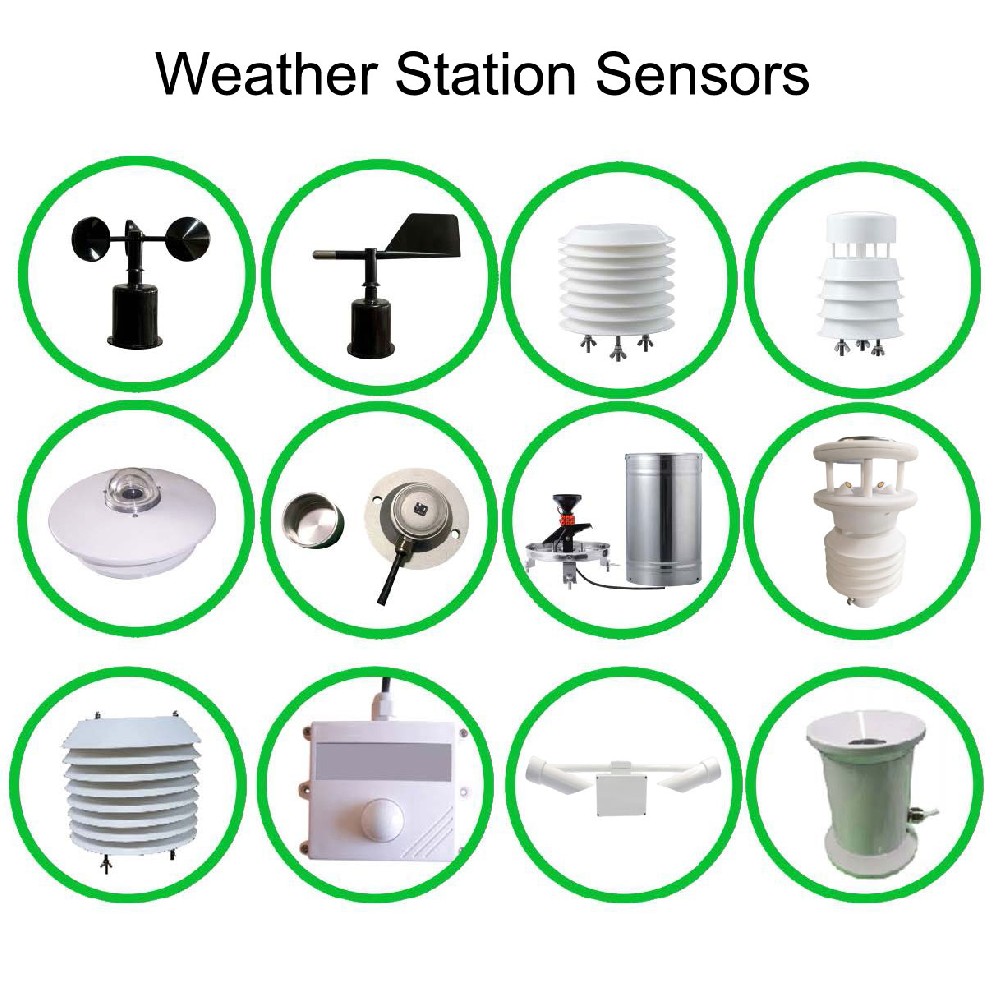
At very low speed, direction can vary without representing a sustained directional flow. Check how the instrument and application handle that condition. Ordinary averaging of angles near north can also mislead: 359 and 1 degrees are close, not opposite directions. Use the defined wind-statistic calculation rather than an arithmetic mean of displayed angles.
If spikes coincide with a fan, engine or transmitter switching on, record that timing without immediately declaring interference. Local airflow, mechanical vibration, supply changes and communication faults are different possibilities. A controlled comparison can narrow the cause more effectively than replacing the sensor on suspicion.
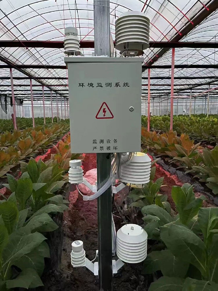
A new screen, growing crop, nearby building or relocated cable can change the observation or installation. An indoor greenhouse point measures local airflow; an open-field wind point has another purpose. Compare the installed position with the observation required by the project before interpreting disagreement as instrument failure.
For a consistent direction offset, inspect mounting orientation and any configured correction. The installation guide addresses reference alignment and moving platforms. Keep alignment diagnosis separate from missing-data troubleshooting, and avoid applying two corrections at different layers.
After a permitted cleaning, connection repair or configuration correction, verify fresh local readings and the final time-stamped record. Keep the service interval identifiable. An instrument resuming replies does not automatically repair historical gaps, and test values should not silently become operational observations.
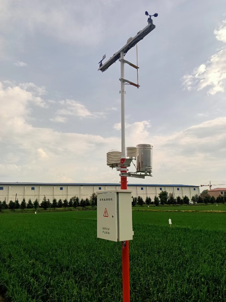
For support, provide the exact model, supply measured at the head, serial settings, affected channels, raw replies, observation times, site conditions and the changes already made. Photographs of the mounting and connections can support diagnosis. Avoid repeated resets that erase the pattern without identifying the fault.
No. It can be a valid measurement, a stale value or an application substitute for missing data. Check fresh instrument replies, timestamps and validity before deciding whether the site is calm.
It has no rotating cup bearings, but still needs appropriate inspection of measurement paths, surfaces, mounting and connections. The permitted cleaning procedure and site findings should guide service work.
Weak or variable flow gives direction a different significance from sustained wind. Review the speed and the configured calm/averaging rules. Do not diagnose a fault from direction alone without the accompanying record.
No. Check the named model and ordered version. For example, NBL-W-51MUWS and NBL-W-61MUWS have different stated operating-temperature limits even though both use RS485 and a DC 12-24 V supply.
After checking supply, communication, decoding, exposure and permitted inspection, provide the evidence to the support team. A persistent instrument-side fault may justify repair or replacement; a server timeout or unsuitable mounting point requires a different remedy.
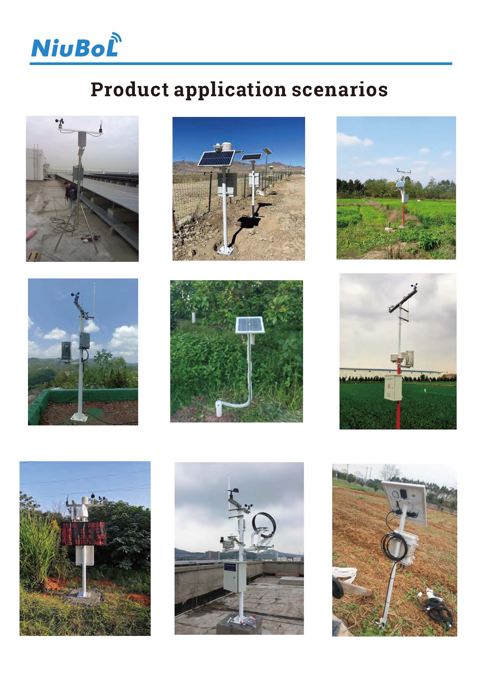
Diagnose an ultrasonic wind sensor by separating communication, measurement validity and exposure. Preserve the original settings, inspect the relevant layer and verify fresh records after intervention. This gives the project a defensible repair decision without confusing calm wind, stale data and a failed instrument.
Configurable all-in-one ultrasonic weather sensor instruction manual.
 All-in-One-Ultrasonic-Weather-Sensor-Instruction-Manual.pdf
NBL-W-61MUWS six-parameter weather sensor instruction manual.
NBL-W-61MUWS-Ultrasonic-Weather-Station-Instruction-Manual.pdfNBL-W-51MUWS five-parameter weather sensor instruction manual.
NBL-W-51MUWS-Ultrasonic-Integrated-Weather-Sensor-Instruction-Manual.pdfNBL-W-21MUWS wind speed and direction sensor instruction manual.
NBL-W-21MUWS-Ultrasonic-wind-speed-and-direction-sensor-instruction-manual.pdfPrev:Weather Station Data Workflow: Preserve Observations, Flags and Revisions
Next:Wind Sensor Selection: Outdoor Weather, Duct Flow or Laboratory?
Related recommendations
Sensors & Weather Stations Catalog
 Agriculture Sensors and Weather Stations Catalog-NiuBoL.pdf
Weather Stations Catalog-NiuBoL.pdf
Agriculture Sensors Catalog-NiuBoL.pdf
Water Quality Sensor Catalog-NiuBoL.pdf
Related products
 Combined air temperature and relative humidity sensor
 TDR Soil Moisture & Temperature Sensor for irrigation| RS485 |4-20mA| NBL-S-THR
 Soil pH sensor RS485 soil Testing instrument soil ph meter for agriculture |NBL-S-PH
 Wind Speed sensor Output Modbus/RS485/Analog/0-5V/4-20mA
 Tipping bucket rain gauge for weather monitoring auto rainfall sensor RS485/Outdoor/stainless steel
 Pyranometer Solar Radiation Sensor 4-20mA/RS485


Screenshot, WhatsApp to identify the QR code
WhatsApp number:+8615367865107
(Click on WhatsApp to copy and add friends)

