
— Blogs —
—Products—
 Consumer hotline +8618073152920
 WhatsApp:+8615367865107
Address:Room 102, District D, Houhu Industrial Park, Yuelu District, Changsha City, Hunan Province, China
Product knowledge
Time:2026-09-01 12:00:00 Popularity:195
Engineers reviewing water conductivity sensor range often discover that conductivity is easy to measure but easy to misuse as a direct concentration or contaminant identity.
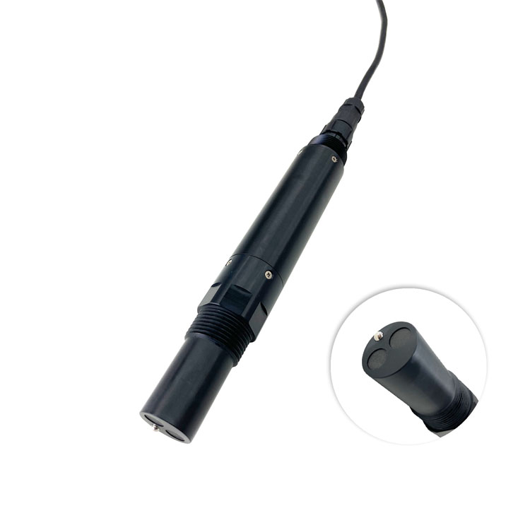
Procurement should enable the team to choose range, temperature compensation and installation from the ionic level and control purpose. That requires a clear measuring point, integration boundary and acceptance method, while recognizing that conductivity cannot identify which ion caused a change and is not a substitute for ion-specific analysis.
Conductivity rises as the concentration and mobility of dissolved ions increase.
Temperature changes ion mobility, so comparable trends require documented compensation and reference temperature.
Low-conductivity purified water and high-salinity wastewater need different cells and ranges even though both report conductivity.
Together, these conditions define the engineering question for water treatment: whether the proposed measurement and system scope can choose range, temperature compensation and installation from the ionic level and control purpose.
| Project item | What the specification should state |
|---|---|
| Operating problem | Conductivity is easy to measure but easy to misuse as a direct concentration or contaminant identity. |
| Required decision | Choose range, temperature compensation and installation from the ionic level and control purpose. |
| Method boundary | Conductivity cannot identify which ion caused a change and is not a substitute for ion-specific analysis. |
| Minimum evidence for water conductivity sensor range | Matched water conductivity sensor range readings, installation record, units, timestamps and a documented acceptance method. |
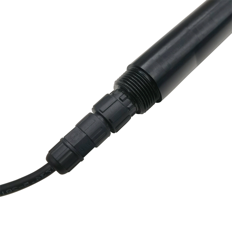
Field challenge: Conductivity rises as the concentration and mobility of dissolved ions increase. At this stage, the engineering risk is that conductivity is easy to measure but easy to misuse as a direct concentration or contaminant identity.
Selection of water conductivity sensor range should begin with the measurement duty, site condition and receiving-system interface. System integration: During design review, the team must write the measurand, unit, compensation and reporting convention into the specification and historian tag.
The water conductivity sensor range record should remain unambiguous across suppliers, controllers and software platforms. This creates a documented basis for the decision to choose range, temperature compensation and installation from the ionic level and control purpose.
Field challenge: Temperature changes ion mobility, so comparable trends require documented compensation and reference temperature. For water conductivity sensor range, site conditions can alter the reported parameter before it reaches the operator, so the full measurement path requires review.
The required class of water conductivity sensor range depends on whether the project needs continuous data, remote alarms or documented handover records. System integration: During design review, the team must control location, timing, temperature, bubbles, settling and sample disturbance according to the measurement principle.
The water conductivity sensor range result should represent the intended water condition, not merely the easiest sampling point. This reduces exposure to the stated problem: conductivity is easy to measure but easy to misuse as a direct concentration or contaminant identity.
Field challenge: Low-conductivity purified water and high-salinity wastewater need different cells and ranges even though both report conductivity. At this stage, the engineering risk is that conductivity cannot identify which ion caused a change and is not a substitute for ion-specific analysis.
Installation quality is part of measurement quality for water conductivity sensor range, so exposure and service access must be checked together. System integration: During design review, the team must compare synchronized results with stated uncertainty and keep every conclusion inside the validated method boundary.
The water conductivity sensor range result should support a conclusion that can withstand technical review. The conclusion remains subject to this stated constraint: conductivity cannot identify which ion caused a change and is not a substitute for ion-specific analysis.
Before comparing models, classify the point as an indicator, alarm, compliance-support or control measurement. Add expected values and matrix conditions from water treatment rather than relying on a generic application label.
A nominally compatible sensor can still be the wrong purchase because conductivity cannot identify which ion caused a change and is not a substitute for ion-specific analysis. Close the technical and operating gap before selecting cable, mounting or controller options.
Price comparison needs an itemized bill of supply. One supplier may quote only the conductivity probe while another includes mounting, communications, cleaning parts and site support; those totals are not equivalent.
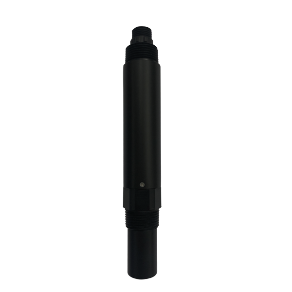
The signal path starts at the conductivity probe and ends only when a usable value reaches the responsible operator. Within the water conductivity sensor range supply scope, define who provides the controller, PLC mapping, gateway, historian tag and maintenance status before placing the order.
The referenced digital route for water conductivity sensor range is RS485 with Modbus RTU. Technical acceptance needs to cover bus polarity, address conflicts, serial format, register conversion and loss-of-communication behavior as well as physical shielding and junction sealing.
For water treatment, keep raw values and quality flags alongside the displayed result so technicians can distinguish a water event from a communication or maintenance fault.
For water conductivity sensor range, the table uses the current NBL-WQ-EC conductivity sensor manual as a verified reference. It defines a realistic engineering option for water treatment; it does not remove the project constraint described above. For water conductivity sensor range, the project requires the final configuration, range and accessories should be confirmed against the quotation and project water data.
| Parameter | Verified reference |
|---|---|
| Reference model | NBL-WQ-EC |
| Ranges for water conductivity sensor range | 0-20.00, 0-200.0, 0-5000 uS/cm or 0-200.0 mS/cm by configuration |
| Accuracy for water conductivity sensor range | +/-1% F.S.; temperature +/-0.3 deg C |
| Compensation for water conductivity sensor range | Pt1000 automatic temperature compensation |
| Output | RS485, Modbus RTU |
| Power | 12-24 VDC; 0.2 W at 12 V |
| Working condition | 0-50 deg C; below 0.6 MPa |
| Protection | IP68 |
| Installation | Immersion, 3/4 NPT |
| Cable | 5 m standard; customizable |
For work in water treatment, nominal accuracy is only one part of suitability.
The quotation for water conductivity sensor range should distinguish the field device, accessories, controller interface and site-service scope. Acceptance for the reported parameter must cover installation, stable response, unit, range, communications, alarms and the comparison method. A number on the display proves data transfer, not measurement quality.
Agree the reference procedure and tolerance before testing. A valid comparison accounts for time, location, stabilization and uncertainty on both sides of the water treatment measurement.
Acceptance documents for water conductivity sensor range should follow the delivered hardware and configured data path. Record the as-built cable route, device address, Modbus settings, scaling, alarm tests and responsible service contact. Include evidence that the point recovers correctly after power and network interruption.
Define the complete duty for the conductivity probe: matrix and range, location, mechanical arrangement, electrical interface, communication, quantity and acceptance purpose. The water conductivity sensor range offer should identify every missing site input as an explicit assumption.
Bid details for water treatment should cover quantity, destination, delivery date, documentation language, packaging, spares, calibration accessories and commissioning. Custom cable, analog output, holder, flow cell or gateway can affect price and lead time.
The main commercial risk is not simply an inaccurate reading. If conductivity is easy to measure but easy to misuse as a direct concentration or contaminant identity, the owner may approve a design or operating response that cannot choose range, temperature compensation and installation from the ionic level and control purpose.
For water conductivity sensor range, a repeat order is reliable only when range, material, output, cable and accessories match the original duty.
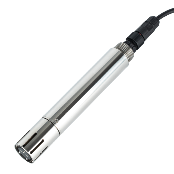
A1: The selected water conductivity sensor range method can establish the stated measurement or trend within its documented limits. It cannot cross this boundary: conductivity cannot identify which ion caused a change and is not a substitute for ion-specific analysis Additional analysis is needed for properties the method does not identify.
A2: Results for water conductivity sensor range are not directly comparable when temperature references, reporting bases, optical conventions or sample preparation differ. Keeping the full water conductivity sensor range measurement basis prevents false comparison during handover and later data review.
A3: For water conductivity sensor range, check the interferences relevant to the selected principle, including bubbles, particles, color, temperature, pH, salinity, redox chemistry, ion competition and sample disturbance.
A4: For water conductivity sensor range, confirm polarity, address, baud rate, parity, register, unit and decimal scaling from the field device to the PLC, RTU or data logger. Then test stale-data handling, communication loss and restart recovery. For context, Low-conductivity purified water and high-salinity wastewater need different cells and ranges even though both report conductivity.
A5: For water conductivity sensor range, use the same location and time after stabilization. For the water conductivity sensor range measuring point, record sample handling, temperature, units, method and uncertainty; one unmatched grab sample is not enough to approve or reject an online point. At this water treatment point, remember that conductivity is easy to measure but easy to misuse as a direct concentration or contaminant identity.
A6: The cited product family includes 0-20.00, 0-200.0, 0-5000 uS/cm or 0-200.0 mS/cm by configuration. When integrating water conductivity sensor range, this is a manual-based reference, not automatic model approval; routine values, credible peaks and the water matrix still control final selection. This requirement helps the team choose range, temperature compensation and installation from the ionic level and control purpose.
A7: The water conductivity sensor range quotation should separate the sensor, holder or flow cell, cable options, controller, gateway, cabinet, calibration items, consumables, spares, documentation, commissioning and freight. Within the water conductivity sensor range supply scope, this prevents a smaller supply scope from appearing cheaper than a complete point. For context, Conductivity rises as the concentration and mobility of dissolved ions increase.
A8: For a water conductivity sensor range inquiry, send water data, photographs or drawings, required output, cable distance, quantity, destination and schedule. Include the current problem: conductivity is easy to measure but easy to misuse as a direct concentration or contaminant identity. In the water conductivity sensor range acceptance plan, that detail lets engineering review suitability before price is issued.
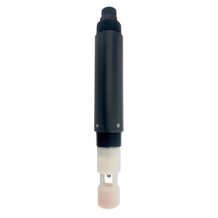
A final specification addressing water conductivity sensor range should connect site conditions to an operator decision and an acceptance test. Its purpose is to choose range, temperature compensation and installation from the ionic level and control purpose; its limit is that conductivity cannot identify which ion caused a change and is not a substitute for ion-specific analysis.
Send NiuBoL the water data, drawing, range, cable and interface requirements, quantity and destination. The resulting offer should separate field device, mechanical accessories, controls, service items and commissioning. A complete water conductivity sensor range package is appropriate when power, logging, communication and mounting responsibilities must remain coordinated.
Prev:Secondary Water Supply Quality Problems: Monitoring Points and Sensor Selection
Next:Residual Chlorine Monitoring in Water Treatment: Measurement Point and Instrument Scope
Related recommendations
Sensors & Weather Stations Catalog
 Agriculture Sensors and Weather Stations Catalog-NiuBoL.pdf
Weather Stations Catalog-NiuBoL.pdf
Agriculture Sensors Catalog-NiuBoL.pdf
Water Quality Sensor Catalog-NiuBoL.pdf
Related products
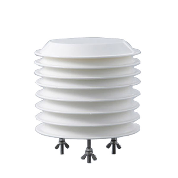 Combined air temperature and relative humidity sensor
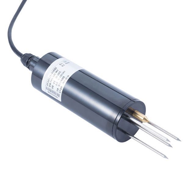 TDR Soil Moisture & Temperature Sensor for irrigation| RS485 |4-20mA| NBL-S-THR
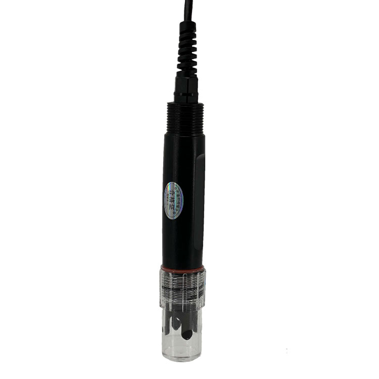 Soil pH sensor RS485 soil Testing instrument soil ph meter for agriculture |NBL-S-PH
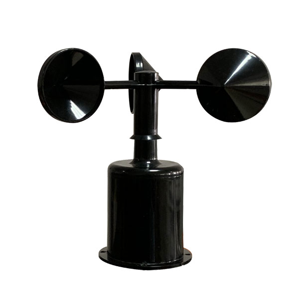 Wind Speed sensor Output Modbus/RS485/Analog/0-5V/4-20mA
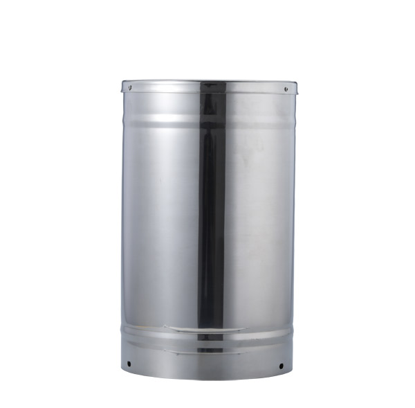 Tipping bucket rain gauge for weather monitoring auto rainfall sensor RS485/Outdoor/stainless steel
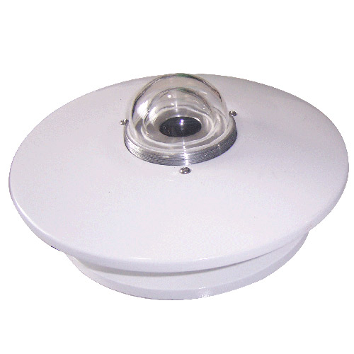 Pyranometer Solar Radiation Sensor 4-20mA/RS485
Screenshot, WhatsApp to identify the QR code
WhatsApp number:+8615367865107
(Click on WhatsApp to copy and add friends)