





— Blogs —
—Products—
 Consumer hotline +8618073152920
WhatsApp:+8615367865107
Address:Room 102, District D, Houhu Industrial Park, Yuelu District, Changsha City, Hunan Province, China
Product knowledge
Time:2026-09-07 16:27:31 Popularity:278
Compare 2D vs 3D wind sensors by the wind quantities the project must record. A two-dimensional instrument measures horizontal wind speed and direction. A three-dimensional instrument also resolves the vertical component, allowing analysis of the wind vector in three axes. Routine weather reporting does not automatically need a vertical channel. Research involving vertical airflow does, but it also needs suitable sampling performance, synchronization and installation geometry; the label “3D” alone does not establish those capabilities.
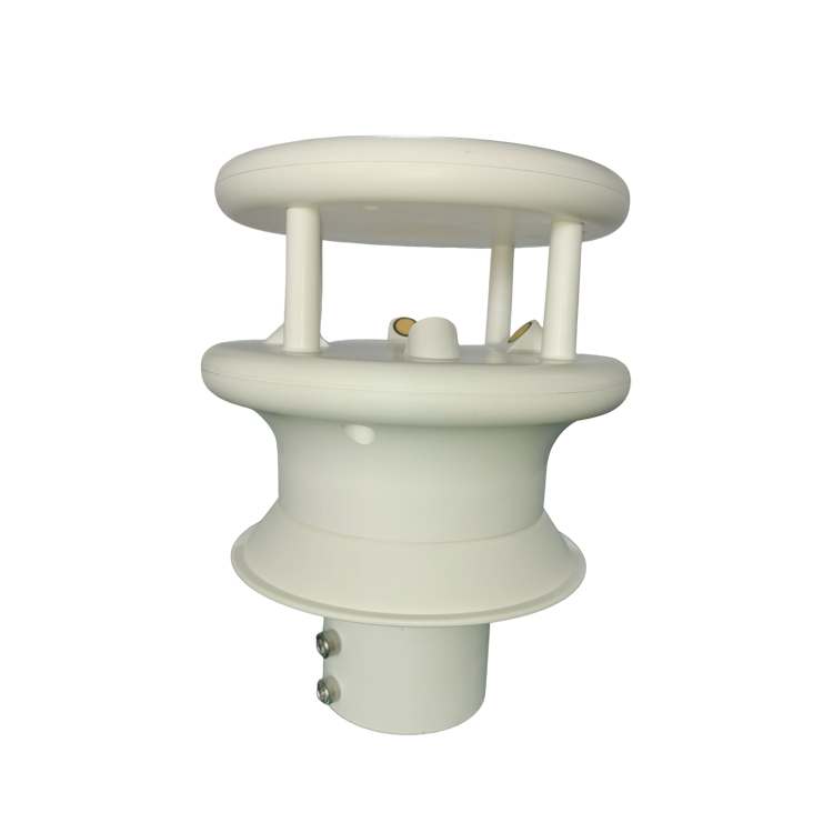
An agricultural weather station may need wind direction for spray decisions and wind speed for local weather records. A photovoltaic site may need a horizontal wind channel alongside irradiance and temperature. Neither requirement, by itself, justifies purchasing a third measurement axis.
By contrast, a study of upward and downward airflow near terrain, structures or a canopy needs a vertical velocity measurement. A horizontal-only sensor cannot reconstruct that missing component from speed and direction, even when a data logger performs additional calculations.
| Required result | Suitable starting point | Selection boundary |
|---|---|---|
| Horizontal speed and direction | 2D ultrasonic sensor or a compatible cup-and-vane pair | Compare low-speed behavior, accuracy, maintenance and output compatibility |
| Vertical velocity and three-axis airflow | 3D ultrasonic sensor | Confirm axis definitions, signed values and the required recording rate |
| Atmospheric turbulence or flux calculations | A measurement system qualified for the study | Validate bandwidth, timing, coordinate corrections and any companion analyzer; 3D geometry alone is insufficient |
| Earth-referenced wind on a moving platform | Wind sensing plus orientation and motion data | A third wind axis does not replace heading, platform velocity or motion compensation |
Ask the end user to name the output they will actually use: a ten-minute mean, a defined gust, a direction sector, an instantaneous vertical velocity or a synchronized velocity record. These are different deliverables. Buying more channels does not resolve an unspecified averaging period or an incorrect definition of wind direction.
Mechanical cup anemometers and wind vanes remain relevant when a station already has suitable inputs and routine service access. Cups provide speed through rotation; a vane follows horizontal direction. They have a starting threshold and moving components that need inspection, but replacing one channel can be straightforward in a compatible existing station.
NiuBoL NBL-W-SS wind speed and NBL-W-DS wind direction sensors are separate instruments. Select the output version to match the receiver: a pulse counter, analog input and RS485 port are not interchangeable. An existing pulse-input logger does not read an ultrasonic Modbus sensor merely because the new sensor also measures wind speed.
Ultrasonic sensing avoids rotating cups and vanes by using acoustic transit times. That can reduce mechanical service tasks, especially at less accessible sites. It does not make the sensor maintenance-free. Contamination, icing, damaged transducers, loose mounting and obstructed acoustic paths can still affect the measurement.
For a conventional replacement, compare the mechanical and ultrasonic measurement approaches first. The remaining distinction here is whether the application requires only horizontal wind or an additional measured vertical component.
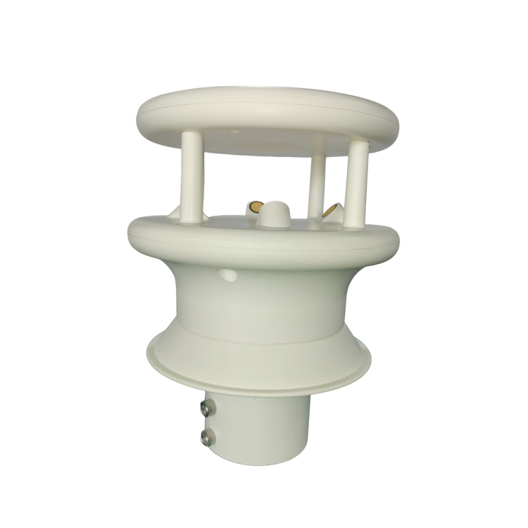
The NBL-W-21GUWS two-in-one ultrasonic anemometer combines horizontal speed and direction in one assembly. The NBL-W-3D-UWDS three-dimensional anemometer adds three-axis wind information. The following comparison identifies the electrical and measurement differences that affect the logger design.
| Parameter | NBL-W-21GUWS | NBL-W-3D-UWDS |
|---|---|---|
| Wind quantities | Horizontal speed and direction | Resultant wind speed, horizontal and vertical angles, X/Y/Z wind components |
| Speed range | 0-60 m/s | 0-60 m/s resultant wind speed; -60 to 60 m/s for axis components |
| Speed resolution | 0.01 m/s | 0.01 m/s |
| Speed accuracy expression | ±(0.5 m/s + 3% FS) | ±(0.5 m/s + 3% FS) |
| Horizontal direction | 0-359 degrees; ±3 degrees accuracy | 0-359 degrees; ±3 degrees accuracy |
| Vertical angle | Not measured | -90 to 90 degrees; ±3 degrees accuracy |
| Supply | 12-24 VDC | 9-24 VDC |
| Communication | RS485 Modbus RTU; 9600 baud | RS485 Modbus RTU; 9600 baud |
| Operating temperature | -20 to 80 C | -40 to 80 C |
| Power consideration | Optional heater rated at 3 W; allow separately for sensing electronics | Average consumption 2 W; check any additional options separately |
FS means full scale, not the instantaneous reading. For a 60 m/s full-scale speed range, the expression above evaluates to ±2.3 m/s. A display increment of 0.01 m/s must therefore not be presented as 0.01 m/s accuracy. Projects needing substantially tighter low-speed uncertainty require a suitable specification and calibration evidence, not just a finer numerical display.
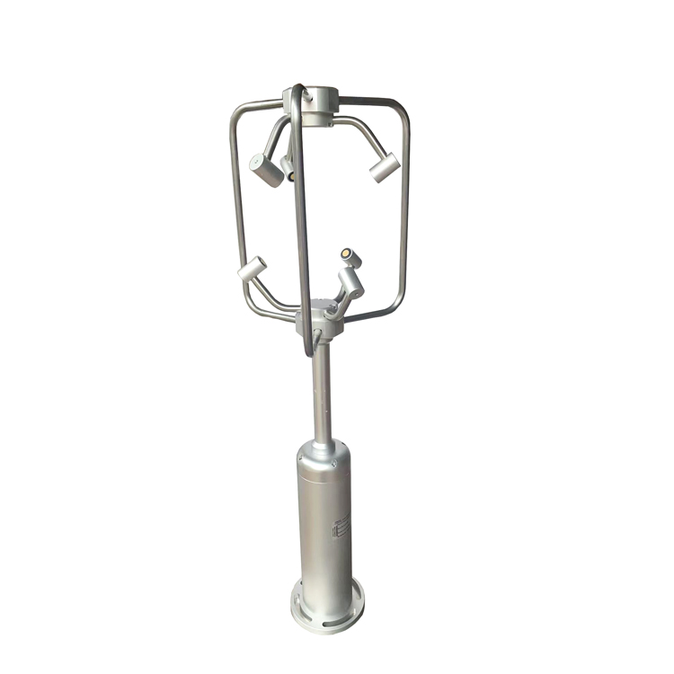
A 3D instrument can separate horizontal movement from upward or downward airflow in its own coordinate system. This is useful when evaluating airflow around a structure or comparing flow at different research positions. It also makes axis orientation part of the measurement: a tilted sensor can project horizontal wind into the reported vertical channel.
For a simple geometric illustration, a 5-degree tilt can project about 0.87 m/s of a 10 m/s horizontal flow onto the tilted vertical axis. That is a mounting effect, not evidence of a genuine updraft. Leveling, surveyed orientation and any subsequent coordinate rotation must be consistent across the study.
The same limitation matters on ships and vehicles. Three-axis sensing describes airflow relative to the instrument. Earth-referenced wind additionally requires the platform's orientation and motion. A compass can provide heading information, but it does not subtract the velocity caused by the vehicle moving through the air.
For turbulence or eddy-covariance work, confirm that the entire acquisition chain preserves the frequencies and time alignment required by the research method. A sensor that supplies three axes at a slow update rate may be useful for mean flow but unsuitable for the intended fluctuations. Do not infer high-frequency research capability from the presence of X, Y and Z registers.
The sensor measurement rate, serial response rate and logger storage interval are separate settings. Polling twice as often does not necessarily create twice as many independent measurements. A cloud dashboard refreshing once per minute also does not show whether the logger captured short events between those updates.
Specify the required statistic before commissioning. A gust value needs a defined averaging window and a measurement chain fast enough to support it. A one-minute stored sample is not automatically the highest gust within that minute. For paired instruments, compare the same averaging periods and timestamps.
Direction needs circular or vector handling. The arithmetic mean of 359 degrees and 1 degree is 180 degrees, although both observations are close to north. Where speed and direction are combined into a vector mean, retain the component calculations and treatment of near-calm conditions. At very low speed, a direction value can become unstable or uninformative even when communication remains normal.
For a PLC, RTU or data logger, RS485 provides the electrical link and Modbus RTU defines the message exchange. Verify register addresses, scale factors, signed-value encoding and axis conventions for the selected device. An unsigned interpretation of a negative component can produce a large positive number that still passes a serial checksum.
A logger intended for only speed and direction may need a different channel configuration for 3D data. Check that it can retain signed X/Y/Z values, the selected direction reference and timestamps without rounding away useful resolution. Verify raw readings at the logger before evaluating a chart that may apply its own unit conversion or smoothing.
Power also changes the installation choice. A 2 W continuous sensor load uses 48 Wh in 24 hours before logger and communication loads are added. Heating can increase the demand further. Use the ordered configuration and actual heater duty assumptions when sizing a solar supply; do not estimate a winter battery from the unheated sensor alone.
Place either sensor where it measures the intended airflow, not the wake of a nearby support or building. For a weather record, representative exposure matters. For research around an obstruction, the disturbed flow may be the subject, but the geometry must be documented so the result can be interpreted and repeated.
IP65 protection on the selected wind speed and direction equipment concerns ingress protection; it is not a complete statement of resistance to salt deposits, corrosion or ice. Consider the exposed materials, connector installation and cleaning access separately. An optional heater also does not establish performance in every icing condition without a defined operating envelope.
Before requesting a NiuBoL configuration, state whether vertical velocity is essential, the speed range and uncertainty required, the recording interval, the site temperature and the receiver interface. Include any existing mast and power limitations. Those details determine whether a 2D instrument, a mechanical replacement or a 3D system is appropriate.
Not necessarily. Three-dimensional sensing adds a measured axis; it does not guarantee lower uncertainty in the horizontal channels. Compare accuracy expressions, operating conditions and calibration results for the particular models.
Not for every monitoring task. Horizontal speed and direction may satisfy the site's weather record. A vertical channel becomes relevant when the project explicitly studies three-dimensional airflow; structural or safety requirements need their own specified measurement system.
Only when the receiver supports the new output and data format. Replacing a pulse-output cup sensor with an RS485 Modbus device requires a compatible serial interface and polling configuration, not a direct connection to the old pulse input.
No. Confirm measurement bandwidth, output rate, timing, coordinate processing and synchronization with the other research instruments. A three-axis channel list is insufficient evidence for a high-frequency flux application.
No. Inspect transducer surfaces, acoustic paths, mounting, connectors and cable condition. Deposits or icing can affect an ultrasonic sensor even though there are no bearings to service.
Use comparable exposure, height, north reference and time windows. Check low-speed behavior separately from moderate wind, and retain individual direction and speed records. For 3D comparisons, also match the axis orientation and signed-component conventions.
Comparing 2D vs 3D wind sensors starts with the required measured quantities. Select horizontal sensing when that answers the operating question; add a vertical channel when the analysis needs it. Then verify uncertainty, timing, power and coordinate handling. An additional axis is valuable only when the installed system can use its data correctly.
Prev:Multi-Parameter Soil Sensors: 2-in-1, 3-in-1, 7-in-1 and Handheld Options
Next:How to Choose 5-in-1, 6-in-1, 7-in-1 and 10-in-1 Integrated Weather Sensors
Related recommendations
Sensors & Weather Stations Catalog
 Agriculture Sensors and Weather Stations Catalog-NiuBoL.pdf
Weather Stations Catalog-NiuBoL.pdf
Agriculture Sensors Catalog-NiuBoL.pdf
Water Quality Sensor Catalog-NiuBoL.pdf
Related products
 Combined air temperature and relative humidity sensor
 TDR Soil Moisture & Temperature Sensor for irrigation| RS485 |4-20mA| NBL-S-THR
 Soil pH sensor RS485 soil Testing instrument soil ph meter for agriculture |NBL-S-PH
 Wind Speed sensor Output Modbus/RS485/Analog/0-5V/4-20mA
 Tipping bucket rain gauge for weather monitoring auto rainfall sensor RS485/Outdoor/stainless steel
 Pyranometer Solar Radiation Sensor 4-20mA/RS485


Screenshot, WhatsApp to identify the QR code
WhatsApp number:+8615367865107
(Click on WhatsApp to copy and add friends)

