





— Blogs —
—Products—
 Consumer hotline +8618073152920
WhatsApp:+8615367865107
Address:Room 102, District D, Houhu Industrial Park, Yuelu District, Changsha City, Hunan Province, China
Product knowledge
Time:2023-11-05 16:16:13 Popularity:9840
An anemometer is an instrument used to measure wind speed or the velocity of moving air. It is widely used in weather stations, agriculture, environmental monitoring, ventilation systems, industrial facilities and wind energy applications.
The working principle of an anemometer depends on its measurement technology. A cup anemometer measures the rotation of wind-driven cups, a propeller anemometer measures the rotation of a rotor, an ultrasonic anemometer measures the propagation time of sound, and a thermal anemometer measures heat transfer from a heated sensing element.
These instruments can all measure wind speed, but their operating principles, response characteristics, maintenance requirements and suitable applications are different.
This guide explains how the main types of anemometers work, how wind speed and direction are measured, and how wind measurements are integrated into automatic monitoring systems.
The primary function of an anemometer is to measure wind speed, usually expressed in meters per second (m/s), kilometers per hour (km/h), miles per hour (mph) or knots.
Some instruments measure only wind speed. Others measure both wind speed and direction, depending on the sensing technology and configuration.
| Parameter | Meaning |
|---|---|
| Wind Speed | Magnitude of air movement at the measurement location. |
| Wind Direction | Direction from which the wind is blowing, generally referenced to geographic north. |
| Mean Wind Speed | Average wind speed over a specified observation period. |
| Wind Gust | Short-duration high wind speed determined according to a defined sampling and averaging method. |
| Wind Components | Directional components of air velocity measured by suitable multi-axis instruments. |
A conventional three-cup anemometer normally measures horizontal wind speed without directly determining wind direction. A separate wind vane can be used for direction measurement.
Certain ultrasonic anemometers can measure both wind speed and direction using one integrated sensing structure.
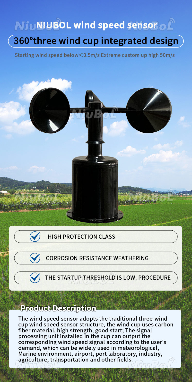
A cup anemometer is one of the most commonly used instruments for measuring outdoor wind speed.
A typical design consists of three hemispherical or conical cups attached to horizontal arms around a vertical rotating shaft.
When wind passes over the cups, aerodynamic forces produce a torque that causes the rotor to turn. The rotational response is related to wind speed.
The sensor detects the speed of rotor rotation using a suitable mechanism, such as magnetic or electronic rotation detection.
The instrument converts the measured rotation frequency into wind speed using a calibration relationship.
Airflow → Cup Rotation → Rotation Detection → Calibration Conversion → Wind Speed
The relationship between rotational frequency and wind speed is approximately linear over the relevant operating range for many cup anemometers, but its exact form depends on the instrument's construction and calibration.
A universal conversion factor should not be applied to every cup anemometer.
Cup anemometers are widely used because of their established measurement method, relatively simple construction and suitability for many outdoor wind monitoring applications.
However, their rotating mechanisms can be affected by bearing friction, mechanical wear, contamination and icing.
At low wind speeds, the rotor may not start until the wind exceeds its starting threshold. Rapid changes in wind speed can also be influenced by the rotor's mechanical inertia and dynamic response.
For NiuBoL's three-cup wind speed sensor, see the NBL-W-SS Wind Speed Sensor.
A propeller anemometer measures air velocity through the rotation of a propeller or vane-like rotor.
The airflow produces aerodynamic forces on the rotor blades, causing them to rotate. The rotational frequency is measured and converted into air speed using the instrument's calibration.
Unlike the vertical-axis construction of a conventional cup anemometer, many propeller anemometers rotate around an axis that is approximately aligned with the airflow.
The response of a propeller anemometer depends on the alignment between the rotor axis and the airflow.
Some outdoor instruments include a directional vane that aligns the propeller assembly with the incoming wind. A combined propeller-vane instrument can provide both wind speed and wind direction.
Handheld vane anemometers are commonly used for airflow measurements in ventilation systems, air ducts and equipment inspection.
The sensor's dimensions, calibration and flow alignment are important when measuring airflow in confined spaces.
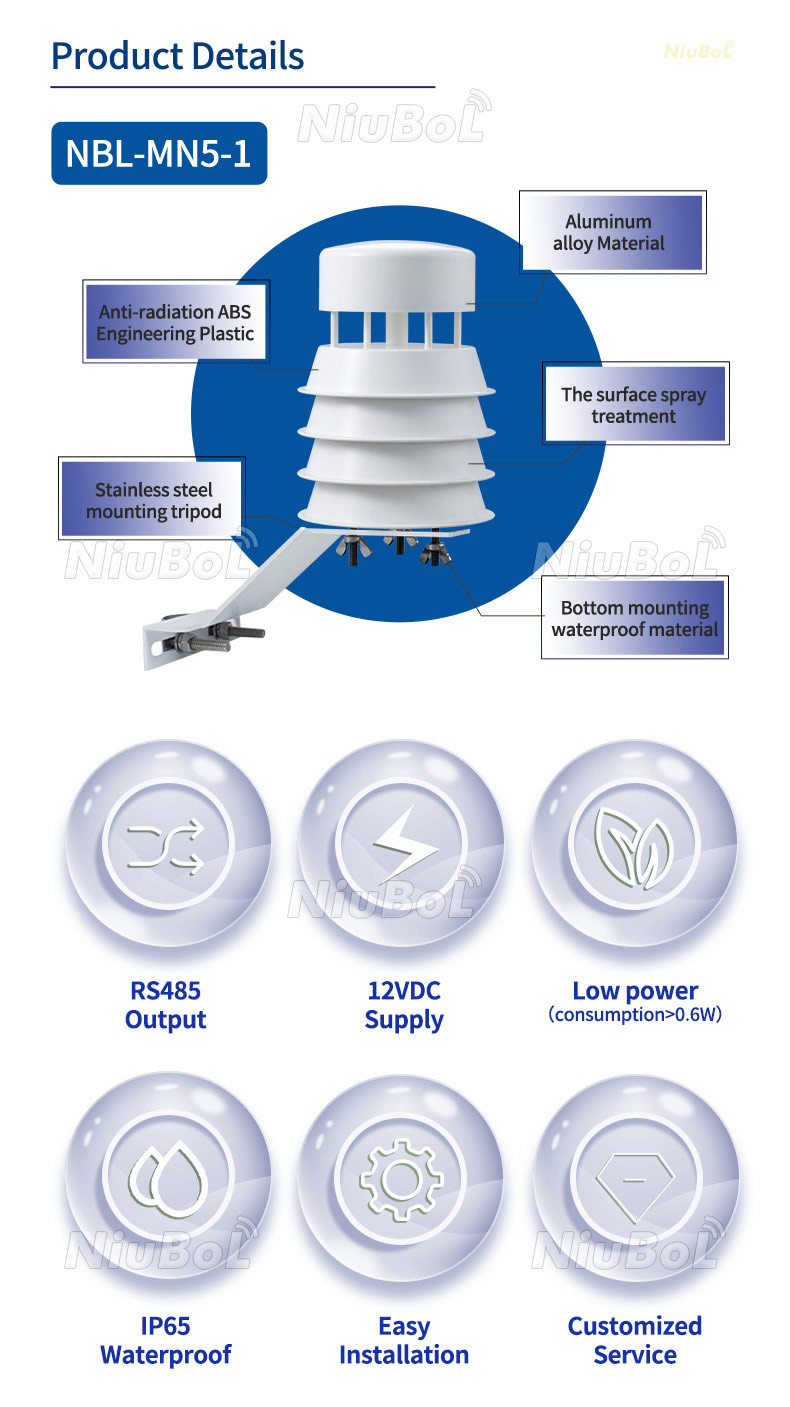
An ultrasonic anemometer measures air velocity using sound propagation rather than the rotation of mechanical components.
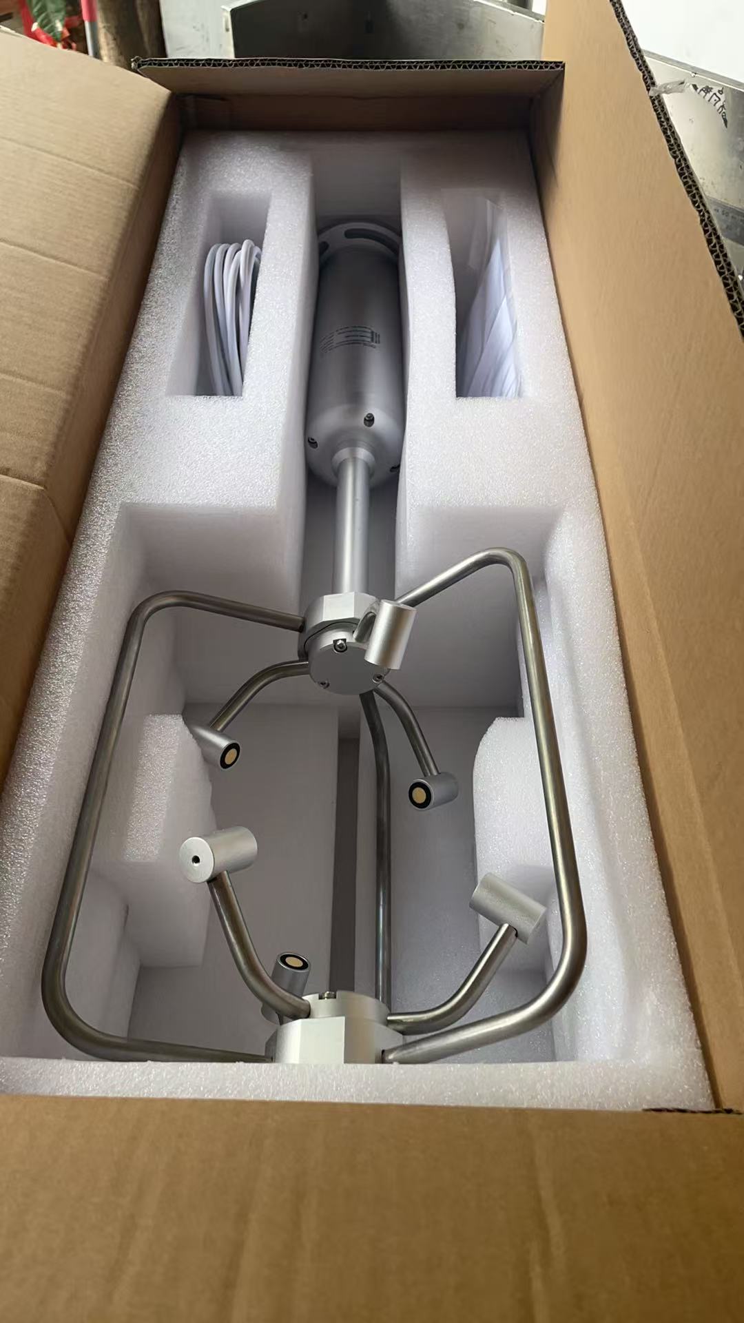
A typical ultrasonic wind sensor contains several acoustic transducers arranged along defined measurement paths.
The instrument transmits ultrasonic signals between transducers and measures the time required for the signals to travel in different directions.
Wind influences the effective propagation speed of sound along a measurement path.
When an ultrasonic signal travels in the same direction as the wind component along that path, its travel time is shorter. When it travels against that wind component, its travel time is longer.
By comparing the transit times in opposite directions, the instrument calculates the wind velocity component along the selected path.
Ultrasonic Transmission → Forward / Reverse Transit Times → Wind Components → Wind Speed and Direction
Two-dimensional ultrasonic anemometers use suitable measurement paths to calculate the horizontal wind vector. Three-dimensional instruments use additional measurement geometry to determine the vertical component as well.
The speed of sound in air depends on environmental conditions, especially temperature.
Bidirectional transit-time measurements help distinguish the effect of wind from the underlying speed of sound. However, real instruments still require suitable signal processing and may use environmental compensation.
It is not correct to claim that ultrasonic measurement is completely unaffected by temperature or other environmental conditions.
Ultrasonic sensors do not require rotating cups or propellers. This removes certain sources of mechanical wear and avoids the starting friction associated with rotating instruments.
Suitable ultrasonic designs can provide wind speed and direction measurements with fast electronic sampling.
However, performance may still be influenced by transducer geometry, precipitation, ice accumulation, contamination, airflow distortion and the instrument's measurement algorithm.
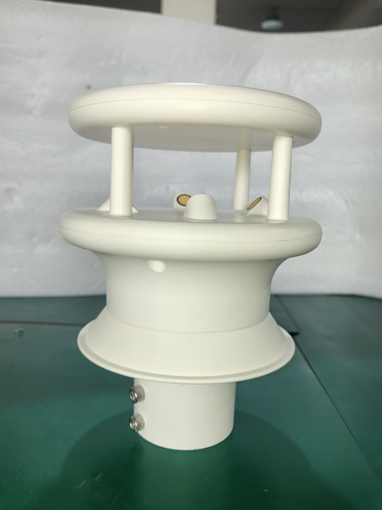
For a NiuBoL product example, see the NBL-W-21MUWS Ultrasonic Wind Speed and Direction Sensor.
A thermal anemometer measures air velocity by observing heat transfer from a heated sensing element to the surrounding airflow.
A conventional hot-wire anemometer contains a very fine electrically heated wire. When air flows past the wire, convective cooling changes the wire's temperature and electrical characteristics.
The measurement electronics determine air velocity using the relationship between heat transfer and the airflow.
In a constant-temperature hot-wire anemometer, the electronic circuit adjusts electrical heating power to maintain the sensing element at a defined temperature condition.
As airflow increases, the cooling effect generally increases. The electrical power required to maintain the element's temperature changes accordingly.
The instrument converts this electrical response into air velocity using an appropriate calibration model.
Airflow → Heat Transfer from Heated Element → Electrical Response → Air Velocity
Thermal anemometers are often useful for measuring low air velocities, studying ventilation flows and performing laboratory airflow measurements.
Certain hot-wire designs offer high-frequency response suitable for studying airflow fluctuations and turbulence.
However, delicate heated elements may be sensitive to contamination, mechanical damage and changing air temperature. A laboratory hot-wire instrument should not automatically be considered suitable for unattended long-term outdoor weather monitoring.
A Pitot tube is another instrument used to measure fluid velocity. It operates through pressure measurement rather than mechanical rotation, ultrasound or electrical heating.
A Pitot-static arrangement measures a pressure difference related to the dynamic pressure of moving air.
With appropriate density information and operating assumptions, the pressure difference can be used to calculate air velocity.
Pitot tubes are commonly associated with aerodynamic testing, aircraft measurements and air duct investigations.
The instrument must be used within the conditions appropriate to its design, including suitable airflow alignment and pressure measurement capability.
| Type | Working Principle | Typical Application | Considerations |
|---|---|---|---|
| Cup Anemometer | Wind-driven cup rotation | Outdoor weather monitoring | Starting threshold, wear and mechanical response |
| Propeller / Vane | Airflow-driven propeller rotation | Weather and ventilation measurements | Flow alignment and rotor response |
| Ultrasonic | Difference in sound transit times | Weather stations and wind-vector monitoring | Transducer exposure, contamination and signal processing |
| Hot-Wire / Thermal | Convective cooling of heated element | Low-speed airflow and laboratory work | Contamination, fragility and thermal compensation |
| Pitot Tube | Pressure difference related to airflow velocity | Ducts and aerodynamic testing | Flow alignment, air density and pressure resolution |
Each technology has different operating characteristics. Sensor selection should be based on the required wind speed range, measurement accuracy, response time, environmental conditions and data acquisition requirements.
Wind speed and wind direction describe different properties of airflow.
Wind speed represents the magnitude of air movement. Wind direction indicates the direction from which the wind originates.
For example, a northerly wind blows from the north toward the south.
A conventional cup anemometer generally measures wind speed, while a separate wind vane determines wind direction from its orientation.
The wind vane should be correctly aligned during installation so that its reported angles correspond to the intended directional reference.
For a compatible wind direction instrument, see the NiuBoL Wind Direction Sensor.
A suitable two-dimensional ultrasonic anemometer determines horizontal wind components along its measurement paths.
The instrument processes these components to calculate horizontal wind speed and direction.
The result must be interpreted according to the sensor's orientation and directional reference. Incorrect alignment can produce a systematic wind direction error.
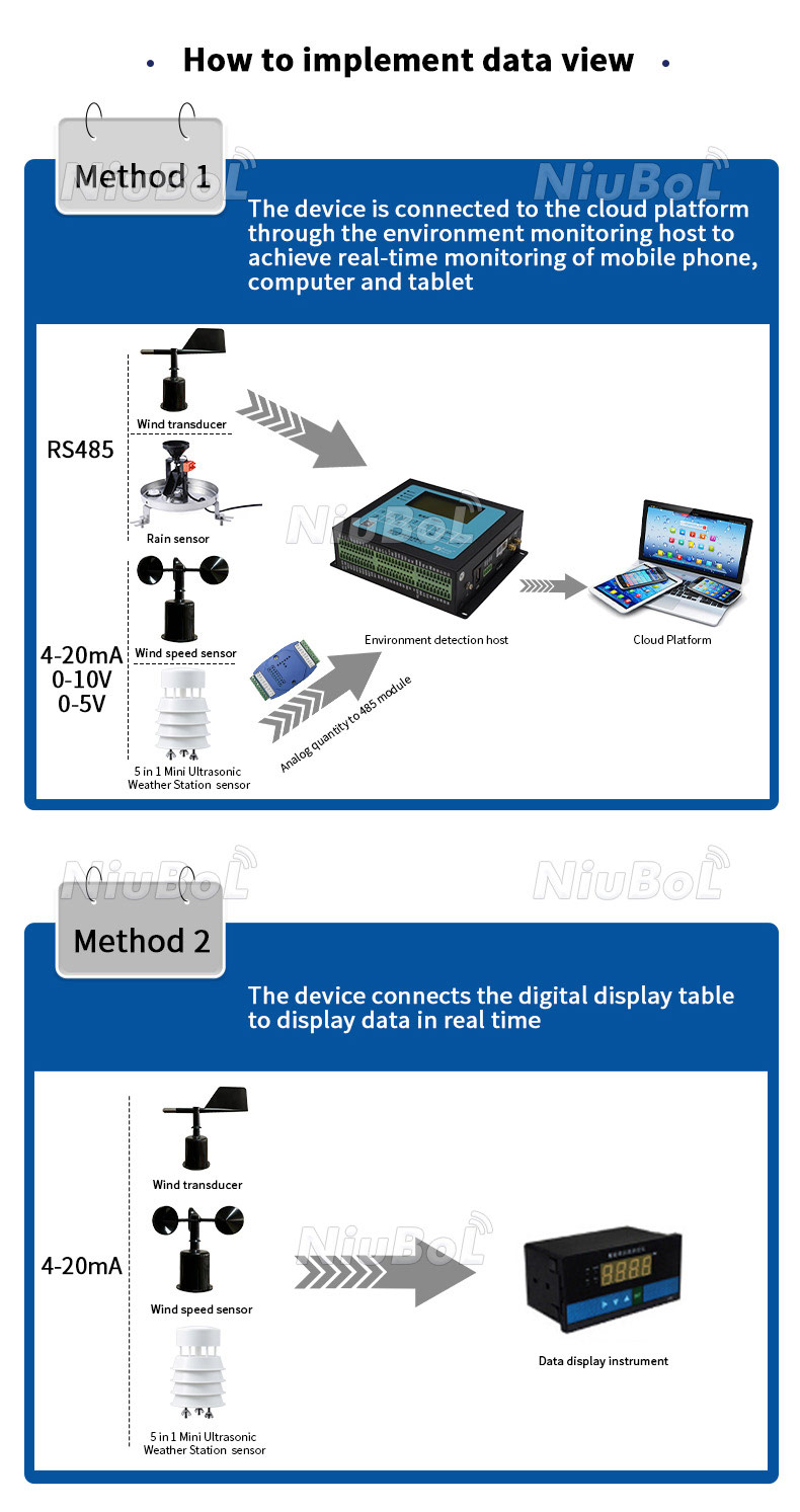
Modern anemometers can provide different types of measurement signals for connection to suitable monitoring and control equipment.
The available output type depends on the sensor model and selected configuration.
| Output | How It Is Used |
|---|---|
| Pulse / Frequency | A compatible receiving device measures signal frequency or counts events and applies the sensor-specific conversion. |
| 4–20 mA | A compatible analog input converts the current signal into wind speed using the configured range. |
| 0–5 V or Other Voltage | A compatible voltage input measures the signal and applies the configured scaling. |
| RS485 Modbus RTU | A PLC, RTU or data logger reads the sensor's documented measurement registers. |
For example, the NiuBoL NBL-W-SS cup anemometer has model configurations supporting pulse, current, voltage and RS485 outputs.
These interfaces should not be treated as interchangeable. The data logger must use the electrical input and conversion method appropriate to the ordered output version.
An RS485 connection provides local wired communication. Cloud transmission requires a compatible data logger, communication gateway and network connection.
Anemometers provide wind speed observations for automatic weather stations, meteorological monitoring networks and atmospheric studies.
Wind measurements can be collected at defined intervals and processed into mean wind speed, gust measurements or other quantities supported by the acquisition system.
Wind speed and direction measurements can support agricultural weather observation and environmental assessment.
Wind conditions are relevant to irrigation spray drift, pesticide application planning, crop exposure and other agricultural operations.
The suitability of a particular operation cannot be determined from wind speed alone. Additional environmental, equipment and regulatory conditions may apply.
Wind measurements are used in wind resource studies, equipment monitoring and engineering applications.
Professional wind energy measurements may require calibrated instruments, defined mounting arrangements and documented measurement procedures.
A general-purpose wind speed sensor should not automatically be considered suitable for every formal wind turbine performance or resource assessment standard.
Wind speed and direction are useful inputs for assessing atmospheric transport and dispersion conditions.
However, an anemometer does not directly measure pollutant concentration. Air quality monitoring requires suitable pollutant sensors or analytical instruments.
Propeller, thermal and other suitable anemometers can be used to evaluate airflow in ventilation ducts, industrial facilities and indoor environmental systems.
For duct airflow measurements, the instrument type, measurement location and flow profile influence the results. A single-point air velocity reading may not represent the average velocity across an entire duct.
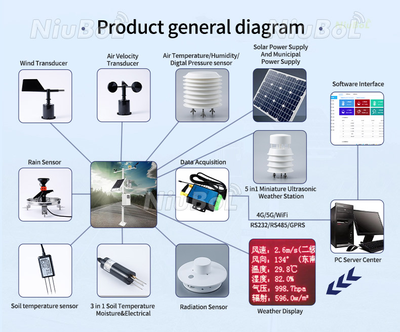
An anemometer provides wind measurement information. Data storage, automatic alarms and remote communication depend on the complete monitoring system.
A compatible data logger can record measurements over time, while an appropriately configured controller or monitoring platform may evaluate wind conditions against defined operating limits.
For example, high wind conditions may be used as an input to an equipment safety interlock or operational alarm. The actual response must be implemented and verified in the relevant controller.
A wind sensor should not be assumed to directly stop machinery, issue cloud notifications or control an industrial process without the required additional equipment.
A typical monitoring arrangement is:
Wind Sensor → Data Logger / PLC → Communication Gateway → Monitoring Platform
Wind measurement quality depends on both the instrument and its installation environment.
| Factor | Potential Effect |
|---|---|
| Buildings and Trees | Can obstruct, accelerate or redirect airflow and create turbulence. |
| Measurement Height | Wind speed can differ between measurement heights. |
| Cup Bearing Condition | Mechanical friction or wear may change the rotor's response. |
| Sensor Alignment | Incorrect orientation can affect directional measurements. |
| Rain, Ice and Contamination | May influence mechanical or ultrasonic sensing performance. |
| Sampling and Averaging | Different observation procedures can produce different reported mean or gust values. |
| Calibration and Signal Scaling | Incorrect conversion factors or data settings may produce inaccurate results. |
For standard surface meteorological wind observations, a height of approximately 10 meters above ground is widely used as a reference. Other heights may be appropriate for agricultural, industrial or specialized monitoring.
The selected measurement height and surrounding exposure conditions should be documented when comparing wind data.
For further installation guidance, read Where Should a Weather Station Be Located and Why?.
The appropriate anemometer depends on the required measurement, environmental conditions and receiving equipment.
For general outdoor wind speed monitoring, a suitable cup anemometer may be sufficient. For wind speed and direction measurements without conventional rotating parts, an ultrasonic sensor may be considered.
For low-speed ventilation studies or laboratory airflow measurements, a suitable thermal or vane instrument may be more appropriate.
Before selection, confirm the measurement range, accuracy, resolution, starting threshold or low-speed response, output type, operating power, environmental protection and mounting requirements.
A1. The principle depends on the type. Cup and propeller anemometers measure airflow-driven rotation, ultrasonic anemometers measure differences in sound propagation time, and thermal anemometers measure heat transfer from a heated sensing element.
A2. Wind produces aerodynamic torque that rotates the cups around a vertical shaft. The sensor measures rotation frequency and converts it to wind speed using a model-specific calibration relationship.
A3. It measures the transit time of ultrasonic signals traveling along defined paths in opposite directions. Differences between the travel times are used to calculate wind velocity components and, for suitable instruments, wind speed and direction.
A4. No. A conventional cup anemometer normally measures wind speed only. Wind direction can be measured with a separate wind vane or by a suitable combined ultrasonic or propeller-vane instrument.
A5. A cup anemometer uses a rotating mechanical structure, while an ultrasonic anemometer measures sound propagation through air. Ultrasonic sensors eliminate the conventional rotating mechanism but remain subject to their own environmental and installation limitations.
A6. A hot-wire anemometer measures airflow through the cooling effect on a heated sensing element. It is commonly used for low-speed airflow measurement and certain laboratory or ventilation applications.
A7. An RS485 anemometer can provide wind measurements to a compatible data logger or gateway. Remote cloud transmission requires appropriate network communication equipment and software configuration.
A8. Both cup and ultrasonic anemometers can be suitable, depending on the required measurements, installation conditions, performance specifications and maintenance objectives. Formal monitoring projects may also specify calibration and observation requirements.
NiuBoL provides wind measurement instruments for weather stations, agricultural monitoring, environmental observation and industrial monitoring systems.
For mechanical wind measurement, see the NBL-W-SS Three-Cup Wind Speed Sensor.
For combined ultrasonic wind speed and direction measurements, see the NBL-W-21MUWS Ultrasonic Wind Speed and Direction Sensor or the NBL-W-21GUWS Ultrasonic Wind Speed and Direction Sensor.
The actual measurement range, accuracy, power requirements and output interface depend on the selected model and configuration.
Download the original NiuBoL NBL-W-SS instruction manual for model-specific technical parameters, output configuration, installation information and communication instructions.
 NBL-W-SS-Wind-Speed-Sensors-Instruction-Manual-V4.0.pdf
For anemometer selection, provide the required wind parameters, measurement range, accuracy, output interface, power supply, installation height, environmental conditions and data acquisition requirements.
Related recommendations
Sensors & Weather Stations Catalog
 Agriculture Sensors and Weather Stations Catalog-NiuBoL.pdf
Weather Stations Catalog-NiuBoL.pdf
Agriculture Sensors Catalog-NiuBoL.pdf
Water Quality Sensor Catalog-NiuBoL.pdf
Related products
 Combined air temperature and relative humidity sensor
 TDR Soil Moisture & Temperature Sensor for irrigation| RS485 |4-20mA| NBL-S-THR
 Soil pH sensor RS485 soil Testing instrument soil ph meter for agriculture |NBL-S-PH
 Wind Speed sensor Output Modbus/RS485/Analog/0-5V/4-20mA
 Tipping bucket rain gauge for weather monitoring auto rainfall sensor RS485/Outdoor/stainless steel
 Pyranometer Solar Radiation Sensor 4-20mA/RS485


Screenshot, WhatsApp to identify the QR code
WhatsApp number:+8615367865107
(Click on WhatsApp to copy and add friends)

