

— Blogs —
—Products—
 Consumer hotline +8618073152920
WhatsApp:+8615367865107
Address:Room 102, District D, Houhu Industrial Park, Yuelu District, Changsha City, Hunan Province, China
Product knowledge
Time:2026-09-19 11:00:00 Popularity:210
Four-electrode conductivity sensor calibration starts by confirming that the ordered instrument actually has a four-electrode cell. Electrode count, cell constant, measurement range and signal wires are different attributes. A model suffix such as 4A or a four-core cable does not establish a four-electrode measuring principle.
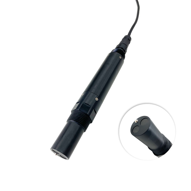
A four-electrode conductivity arrangement separates current-carrying electrodes from potential-sensing electrodes. NIST's publication on electrolytic-conductivity standards describes a four-electrode reference cell with those separate roles. That example explains the distinction; it does not identify the internal design of an unrelated industrial probe.
Request a model-specific cell description and its approved calibration procedure. Contacting two-electrode, contacting four-electrode and inductive designs must not inherit each other's cleaning or adjustment instructions merely because all report conductivity. A sensor body's appearance is not sufficient evidence of electrode count.
| Item on the offer | What it means | What it does not establish |
|---|---|---|
| Four-electrode cell | A specified measuring architecture with separate current and voltage sensing roles | Immunity to deposits, wrong standards or installation effects |
| Cell constant | A factor associated with the cell geometry and its calibrated relationship | The number of sensing electrodes |
| Four-core cable | An electrical cable arrangement | A four-electrode measurement cell |
| 4A model suffix | A designation whose meaning must come from the offered model specification | Automatic proof of four electrodes or four simultaneous water parameters |
Choose a traceable conductivity standard suitable for the instrument range and approved calibration method. Record the standard identity, certified value, reference temperature and the instrument's compensation settings. A compensated value at a reference temperature and an uncompensated value at the actual temperature are not automatically comparable.
Do not use a fixed percentage-per-degree correction without confirming that it suits the selected configuration and liquid. If a comparison differs, check the measured temperature and correction basis before changing the cell adjustment. A temperature mismatch can otherwise be stored as an incorrect calibration factor.
Fully expose the required sensing region, remove trapped air and maintain the approved clearance from the vessel. Use enough standard to avoid a partially immersed cell. Rinse using the approved method without diluting the test portion, and allow temperature and reading to stabilize before an adjustment.
Repeat the observation after a permitted change in vessel position without adjusting calibration. If the result changes with wall distance or immersion, investigate geometry and exposure. Fitting a factor to one unsuitable beaker arrangement does not establish correct field performance.
A multiparameter assembly requires identification of its fitted conductivity module. Its housing, brush or additional parameters do not establish the internal electrode architecture or authorize a different calibration sequence.
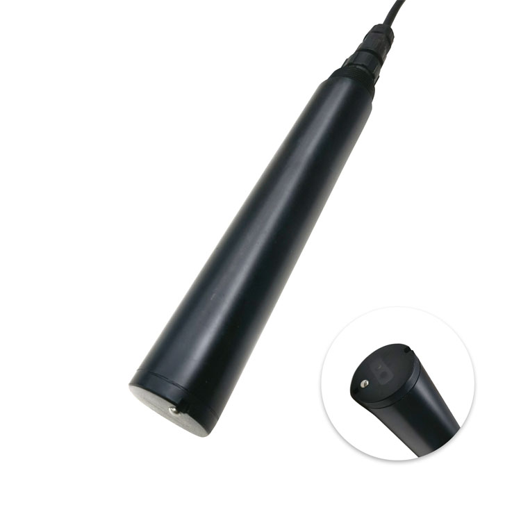
The NBL-WQ-EC family and the NBL-WQ-EC-4A have different documented range and output configurations. The 4A designation alone is not a four-electrode declaration. If four-electrode construction is mandatory, require explicit confirmation before approval.
| Item | Base NBL-WQ-EC | NBL-WQ-EC-4A |
|---|---|---|
| Range options | 0–20 or 0–200 μS/cm; 0–5000 μS/cm; 0–200 mS/cm | 0–5000 μS/cm |
| Accuracy and resolution | ±1% FS; range-dependent resolution | ±1.5% FS; 1 μS/cm resolution; confirm order-specific accuracy basis |
| Temperature compensation | Pt1000-based automatic compensation | Pt1000-based automatic compensation |
| Signal | RS485 Modbus RTU | RS485 Modbus RTU; optional 4–20 mA |
| Supply and consumption | 12–24 VDC; 0.2 W at 12 V | 12–24 VDC; 0.2 W at 12 V |
| Liquid exposure | 0–50 °C; pressure <0.6 MPa | 0–50 °C liquid; pressure <0.6 MPa |
| Mounting and protection | 3/4 NPT immersion mounting; IP68 | 3/4 NPT immersion mounting; IP68 |
| Material and cable | ABS/316L or PVC by configuration; standard 5 m cable | ABS/316L configuration; standard 5 m cable |
For the EC-4A 0–5000 μS/cm range, plan slope calibration with a standard in the 20–100% full-scale band and use the procedure approved for the ordered version. Keep this separate from the base family's calibration settings. Verification near the operating concentration may be needed in addition to calibration.
Once the approved standard check passes, verify the installed cell under representative water conditions. Then compare the local value with the PLC or data logger. Check μS/cm versus mS/cm and the configured decimal field before deciding that a numerical disagreement is an electrode problem.
Use the conductivity cleaning and reinstallation guide for the detailed service sequence. For procurement, send NiuBoL the required cell architecture, range, standard value, temperature basis, installation geometry and host interface. A quote should resolve those items before a calibration routine is approved.
No. The standard must suit the model's range, calibration method and temperature basis. Electrode count alone does not specify a valid calibration concentration.
Do not infer that from the name. Require a specific cell description when four-electrode construction is a project requirement.
No. Deposits, blocked liquid access, trapped air and inappropriate exposure can still affect the complete measurement. Use the cleaning method approved for its actual construction.
No. Check the standard, temperature correction, immersion, clearance and stability first. An adjustment can otherwise conceal an unsuitable test arrangement.
No. It verifies data handling when compared correctly. The cell response in an appropriate standard and the installed exposure require separate checks.
Confirm the cell design before approving a four-electrode calibration procedure. Keep the standard, temperature basis and geometry consistent, then verify the installed value and host scaling separately. Model names and cable counts cannot substitute for those checks.
Prev:TDS, Conductivity and Salinity: Which Parameter Should a Water Project Specify?
Next:Online Turbidity Sensor Selection for Drinking Water and Filter Monitoring
Related recommendations
Sensors & Weather Stations Catalog
 Agriculture Sensors and Weather Stations Catalog-NiuBoL.pdf
Weather Stations Catalog-NiuBoL.pdf
Agriculture Sensors Catalog-NiuBoL.pdf
Water Quality Sensor Catalog-NiuBoL.pdf
Related products
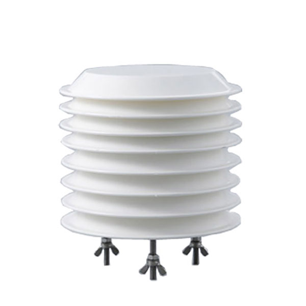 Combined air temperature and relative humidity sensor
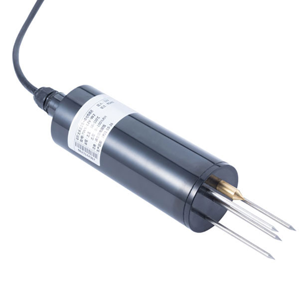 TDR Soil Moisture & Temperature Sensor for irrigation| RS485 |4-20mA| NBL-S-THR
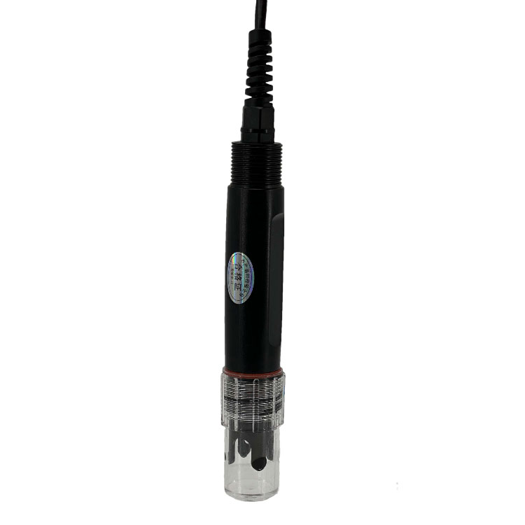 Soil pH sensor RS485 soil Testing instrument soil ph meter for agriculture |NBL-S-PH
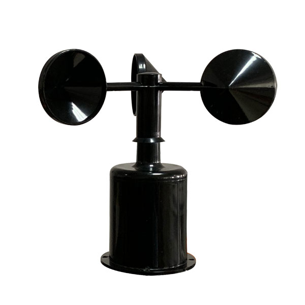 Wind Speed sensor Output Modbus/RS485/Analog/0-5V/4-20mA
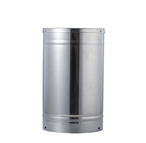 Tipping bucket rain gauge for weather monitoring auto rainfall sensor RS485/Outdoor/stainless steel
 Pyranometer Solar Radiation Sensor 4-20mA/RS485

Screenshot, WhatsApp to identify the QR code
WhatsApp number:+8615367865107
(Click on WhatsApp to copy and add friends)