

— Blogs —
—Products—
 Consumer hotline +8618073152920
WhatsApp:+8615367865107
Address:Room 102, District D, Houhu Industrial Park, Yuelu District, Changsha City, Hunan Province, China
Product knowledge
Time:2026-09-22 08:00:00 Popularity:210
A water quality monitoring buoy system must keep measuring, storing and recovering data through periods of poor sunlight and interrupted communications. Select the sensor configuration first, then size the complete electrical load and confirm the buoy's payload, mooring and retrieval arrangement. RS485 Modbus RTU connects the submerged probes to the onboard logger; it is not the wireless link to shore. A successful sensor demonstration does not prove that the assembled buoy can deliver the required monitoring service.
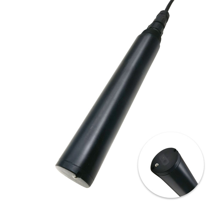
A reservoir buoy observing conditions at one depth has a different job from a river station watching rapid runoff or an aquaculture installation supporting operator alarms. State the required parameters, measurement interval, maximum reporting delay and acceptable outage before selecting the enclosure or solar panel. These requirements determine both energy demand and data handling.
The sensor position also needs a definition. A probe suspended a fixed distance below a floating platform follows the water surface; it does not remain at a fixed elevation above the bed. A single-depth sensor cannot establish a whole-reservoir profile. If the decision depends on vertical differences, specify additional depths or an independently engineered profiling arrangement.
Use water depth, expected level variation, current, waves, debris and access conditions to assess the platform and mooring. Do not choose an anchor mass from the probe's weight alone. A location with reliable cellular coverage may still be unsuitable because of vessel traffic, a local discharge plume or unsafe retrieval access. Mooring and navigation requirements need site-specific assessment.
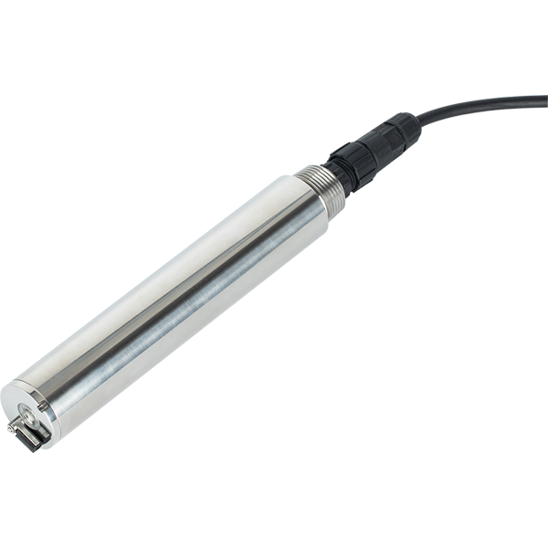
A configurable NiuBoL NBL-WQ-MPS-5B can combine selected DO, pH, ORP, conductivity/salinity and turbidity channels, with temperature, in one immersed assembly. Its shared cable can simplify the buoy connection. It also creates shared exposure to power, communication and retrieval failures, so channel count is not equivalent to independent redundancy.
Where optical COD or ammonium is required, assess an appropriate MPS-5A configuration or separately selected instruments. Do not add parameters merely to fill available positions. Chlorophyll, algae or other specialized duties require their own compatible sensors and validation; they are not implied by the phrase multi-parameter.
| Instrument example | Electrical and measurement data | Buoy-design consequence |
|---|---|---|
| MPS-5B assembly | 12 VDC; rated 2 W at 12 V; RS485 Modbus RTU; IP68; 0-50 degrees C; pressure at or below 0.2 MPa | Regulate supply for the assembly and include cleaning demand in the load test. |
| MPS-5A assembly | 12 VDC +/-5%; rated 5 W at 12 V; RS485 Modbus RTU; standard 5 m cable | A wider parameter configuration can change the energy budget; verify the assembled environmental limits. |
| NBL-WQ-TS-408-S turbidity probe | 0-20, 0-200, 0-1000 or 0-4000 NTU options; 12-24 VDC; rated 0.2 W at 12 V; RS485 Modbus RTU; optional 4-20 mA | Choose the range for expected background and events; verify cleaning peak demand separately. |
| MPS-5B pH and ORP modules | pH 0-14, accuracy +/-0.1; ORP -1500 to +1500 mV, accuracy +/-6 mV | Keep parameter-specific reference checks and consumables in the service plan. |
The TS-408-S is an immersion instrument with an automatic cleaning brush, not a shore-mounted flow cell. Its lowest turbidity range has a 0.01 NTU resolution but an accuracy expression of +/-3% of reading or +/-1.5 NTU, whichever is greater. That distinction matters when a clear-water project expects to detect very small changes. Specify the decision tolerance, not just the largest storm value.
For the MPS cable, four-core twisted-pair shielding describes the electrical construction, not complete resistance to ultraviolet exposure, abrasion or chemicals. Specify the jacket and connector arrangement for the deployment. Support the probe mechanically and leave a controlled service loop; do not make the signal cable carry the mooring or instrument load.
Use energy in Wh/day for battery and solar calculations, and current for cable and protection checks. If an MPS-5B actually draws 2 W continuously, that load alone consumes 48 Wh/day. At 5 W continuously, an MPS-5A consumes 120 Wh/day. Neither figure includes the logger, gateway, voltage conversion, communications retries or other accessories.
Measure the assembled system through sampling, cleaning, transmission and idle states. Confirm whether the quoted sensor power represents the operating state used in the calculation. A short brush or radio peak may be modest in daily energy but still cause a voltage dip that resets the logger. Include both the energy budget and peak-load behavior in the test.
Consider a hypothetical complete buoy using 100 Wh/day. Three days without charging require 300 Wh of usable energy. With an assumed usable battery fraction of 0.8 and delivery efficiency of 0.9, the nominal capacity calculation is 300/(0.8 x 0.9), approximately 417 Wh. At a nominal 12 V this is about 35 Ah. These are arithmetic assumptions, not a NiuBoL battery recommendation; temperature, aging, chemistry and the required reserve must be assessed separately.
Solar sizing needs the site's unfavorable operating season, not an annual average. Under hypothetical assumptions of 2.5 equivalent full-sun hours and 70% total conversion yield, replenishing 100 Wh/day requires about 57 W of panel rating. That calculation only balances average daily use under those assumptions. It contains no allowance for restoring a depleted battery while continuing operation, additional shading or extended poor weather.
A nominal 12 V battery does not maintain a constant 12 V terminal voltage throughout charging and discharge. Provide a suitable regulated supply where the probe requires it, particularly for the MPS-5A's narrow input tolerance. Confirm that low-voltage protection, restart behavior and the power manager do not repeatedly cycle the instruments around the battery cutoff point.
A buoy may measure every five minutes and transmit a batch less frequently, provided that this meets the response requirement. Lower upload frequency does not necessarily reduce sensor energy if probes remain continuously powered. Conversely, switching probes off between readings is only acceptable after validating warm-up, stabilization and cleaning behavior for the ordered configuration.
Specify local storage that continues when the radio link fails. At a five-minute interval, one station creates 288 timestamped measurement sets per day; a seven-day interruption produces 2,016 sets. Calculate memory from the actual record size, including status and diagnostic fields, and leave space for the required outage period and retransmission management.
On reconnection, older records should retain their measurement times rather than acquire the upload time as if they were new readings. Define duplicate handling and the order of delayed uploads. Test the receiving platform with an intentional link interruption, not merely a screenshot of one successful connection.
The onboard gateway must support the chosen local sensor interface and the actual remote service. Cellular coverage, network compatibility, antenna placement and subscriptions belong to that service specification. A Modbus label does not establish cellular connectivity, cloud compatibility or an unlimited radio range.
Fix the immersed package at an identified depth with protection against avoidable impact and abrasion. Keep it away from the platform's own disturbed water where that would bias the measurement. For the TS-408-S, respect its optical clearances, including more than 5 cm from side walls and more than 10 cm from the bottom of a nearby enclosure or vessel used for checking.
Plan safe retrieval of the sensor assembly separately from lifting the entire buoy. The service team should be able to record as-found readings, remove the package, clean and check each channel, then return it to the same defined position. Record changes in sensor depth or mounting because they can explain a trend shift that is otherwise mistaken for calibration drift.
Self-cleaning reduces one maintenance burden but does not inspect the mooring, clear a blocked guard or clean the solar panel. Schedule those checks around site access and actual conditions. A critical remote deployment may justify a spare configured probe so calibration work can be completed ashore without a prolonged data gap.
Before shipment, bench-test the complete sensor, power and logger combination. Before acceptance afloat, verify mechanical security, representative immersion, communication recovery, retained data after a power cycle and reference comparisons at the sensor depth. Preserve the first complete operating record with configuration and service identities, as a baseline for later fault investigation.
No. Add the logger, gateway, conversion losses, cleaning duty and accessory loads, then test the assembled system. Sensor power can dominate some configurations, but communications peaks or battery protection can still determine whether the station resets during service.
No. The rating applies to the specified instrument under its conditions. Above-water enclosures, connectors, cable entries and field joints need their own suitable protection. Water ingress at a single unprotected connection can disable an otherwise suitable submerged probe.
The required behavior should be local timestamped recording, explicit communication status and controlled upload after recovery. Confirm that the selected logger and gateway provide this behavior and sufficient memory. The sensor itself does not guarantee store-and-forward transmission.
Only for a duty defined at that depth. Stratification or intake management may require observations elsewhere in the water column. State whether the depth follows the surface or a fixed elevation and select additional measurement arrangements when the decision requires them.
Provide the water-body location and depth range, currents and waves where known, required parameters and tolerances, sample and upload intervals, outage autonomy, network availability and retrieval method. Identify whether the order includes the platform, mooring, power, logger, gateway and deployment work. This prevents a probe price from being mistaken for a complete installed station price.
Define the allowed data loss, measurement drift, energy reserve and communication recovery, then test under representative conditions. A short successful demonstration cannot establish every-season endurance. Review battery history, reference comparisons and physical condition before extending the operating interval.

A water quality monitoring buoy system is ready for deployment when its sensor duty, power budget, data recovery and retrieval method have been checked together. NiuBoL probes provide the underwater measurements; the chosen logger, gateway, power supply and platform must preserve those measurements throughout the intended deployment. Request a configuration based on the site's operating season and response needs, with explicit tests for energy and communication interruptions.
Prev:Self-Cleaning Multi-Parameter Water Quality Probe for High-Fouling Sites
Next:Solar-Powered River Water Quality Station for Remote Monitoring Projects
Related recommendations
Sensors & Weather Stations Catalog
 Agriculture Sensors and Weather Stations Catalog-NiuBoL.pdf
Weather Stations Catalog-NiuBoL.pdf
Agriculture Sensors Catalog-NiuBoL.pdf
Water Quality Sensor Catalog-NiuBoL.pdf
Related products
 Combined air temperature and relative humidity sensor
 TDR Soil Moisture & Temperature Sensor for irrigation| RS485 |4-20mA| NBL-S-THR
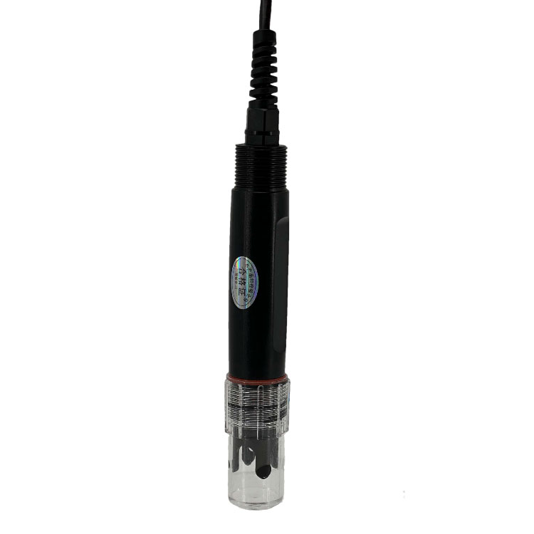 Soil pH sensor RS485 soil Testing instrument soil ph meter for agriculture |NBL-S-PH
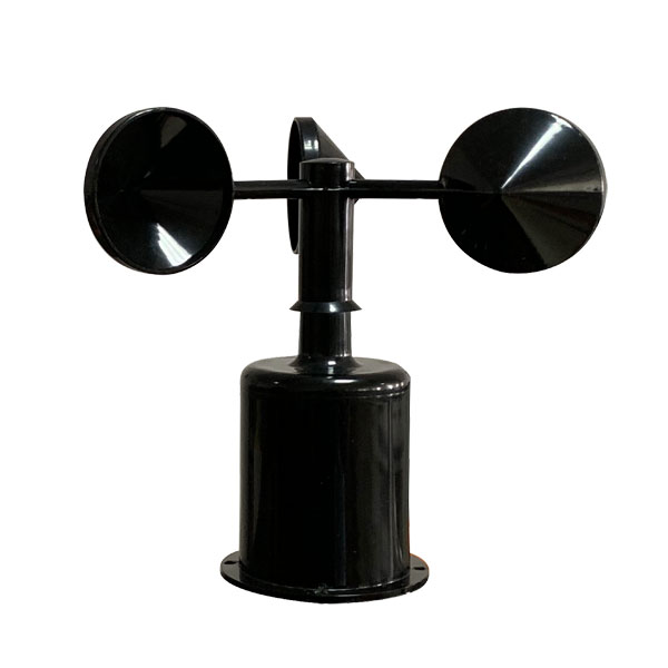 Wind Speed sensor Output Modbus/RS485/Analog/0-5V/4-20mA
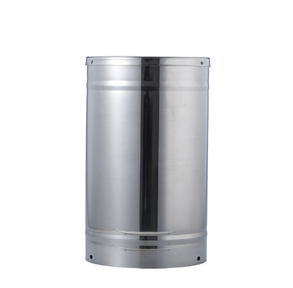 Tipping bucket rain gauge for weather monitoring auto rainfall sensor RS485/Outdoor/stainless steel
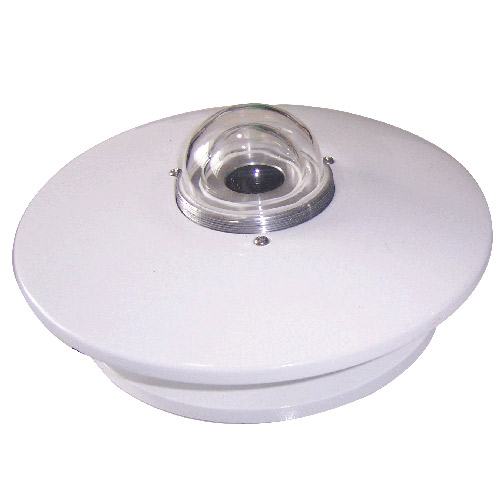 Pyranometer Solar Radiation Sensor 4-20mA/RS485

Screenshot, WhatsApp to identify the QR code
WhatsApp number:+8615367865107
(Click on WhatsApp to copy and add friends)