

— Blogs —
—Products—
 Consumer hotline +8618073152920
WhatsApp:+8615367865107
Address:Room 102, District D, Houhu Industrial Park, Yuelu District, Changsha City, Hunan Province, China
Product knowledge
Time:2026-09-22 10:00:00 Popularity:203
Water quality sensor Modbus registers may contain an integer measurement followed by a separate decimal-place value. Reading those words as one floating-point number, or applying a scale copied from another channel, can produce a plausible but wrong PLC value. Validate the exact NiuBoL register layout and conversion before connecting the result to SCADA trends or alarms.
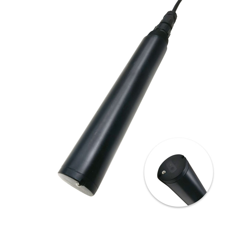
An RS485 link can return valid Modbus RTU responses while the displayed concentration is incorrect. Separate the communication test from the parser test: first establish that the intended instrument answered; then establish what its returned words mean. A successful CRC check cannot identify the wrong engineering unit or scaling rule.
For multi-parameter assemblies, do not assume that a mapping copied from a single turbidity or salinity instrument has the same channel order. Obtain the register layout for the installed assembly and software version. An absent optional module must not become a valid zero simply because its display position has been reserved.
The Modbus Application Protocol Specification defines protocol transactions. The interpretation of a water-quality value still depends on the instrument's register map. Protocol compatibility is therefore necessary for integration, but it does not provide a universal pH, turbidity or salinity data dictionary.
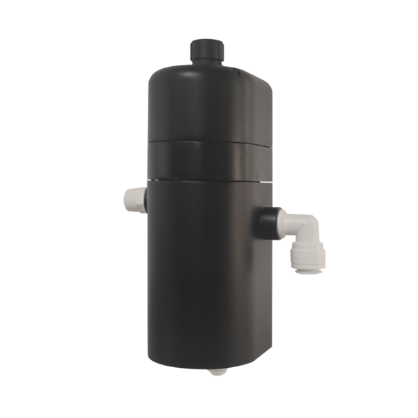
The NBL-WQ-TSA-4 mapping identifies the measurement block as reference 40001 with transmitted starting address 0x0000, read using function 03. The block contains four 16-bit words: measured integer, its decimal-place count, temperature integer and its decimal-place count. A PLC driver may ask for a reference number or a zero-based offset; confirm which convention its input field expects.
For that layout, reconstruct the engineering measurement as the integer divided by ten raised to the returned decimal count. Do not combine the first two words into an IEEE 754 floating-point value. Do not discard the second word because it happens to be unchanged during a short bench test.
| Word in the block | Illustrative raw content | Interpretation for this example |
|---|---|---|
| Measurement integer | 0x0102 = 258 | Raw turbidity numerator, not yet an NTU result |
| Measurement decimal count | 0x0003 = 3 | 258 / 10^3 = 0.258 NTU |
| Temperature integer | 0x00B0 = 176 | Raw temperature numerator |
| Temperature decimal count | 0x0001 = 1 | 176 / 10^1 = 17.6 °C |
These four words are a constructed decoding example within the TSA-4 low range, not a captured installation result or a complete RTU message. A real transaction also includes the address, function, byte count and CRC. Check the returned message length and the requested register count before using the values.
A constant room-temperature reading is a weak parser test. A wrong conversion can look reasonable at one point. Use a controlled test input or recorded response set that includes a small concentration, a changed decimal count and an invalid or incomplete response. Keep synthetic parser tests separate from wet calibration or instrument accuracy tests.
For channels that can legitimately be negative, such as ORP or temperature within an applicable model's range, confirm the signed representation. Interpreting a signed negative integer as unsigned can turn it into a large positive value. Do not decide signedness from the fact that today's water temperature is positive.
| TSA-4 characteristic | Value | Integration implication |
|---|---|---|
| Method and range | 90° scattered light; 0–10.000 NTU | Set the tag unit and range for the ordered instrument. |
| Accuracy | ±5% or ±0.02 NTU, whichever is greater | Confirm the percentage basis; decoding tests do not establish measurement accuracy. |
| Resolution and listed detection limit | 0.001 NTU and 0.1 NTU respectively | Do not describe the reporting increment as the detection capability. |
| Power and output | 12–24 VDC; 0.2 W at 12 V; RS485 Modbus RTU; confirm the ordered 4–20 mA option | Document which interface drives each receiving tag. |
| Working environment | 0–50 °C; pressure ≤0.2 MPa; IP65 | The wall-mounted flow-through instrument is not an immersion probe. |
| Cable and enclosure | Standard 5 m cable; composite housing | Confirm jacket, extensions and waterproof junction details for the installation. |
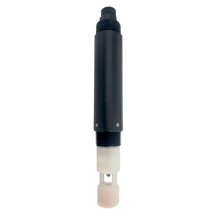
The NBL-WQ-EC-S salinity instrument shown later has a 0–70 PSU range. Keep its salinity tag distinct from conductivity in μS/cm or mS/cm. A correct numeric conversion with the wrong unit remains an incorrect result. Do not manufacture a conductivity value by simply changing the unit label.
Retain the raw words during commissioning, alongside the decoded value, instrument identity and acquisition time. Check that the host conversion matches a supported local indication or independent read of the same response. This lets an engineer distinguish a measurement disagreement from a decoding error without immediately recalibrating the probe.
On timeout, distinguish the most recent valid value from the present data quality. A retained last value can be useful for historical context, but it must not appear fresh. Avoid replacing a failed read with zero, particularly where low DO, low disinfectant residual or a zero-valued process condition has operational meaning.
Define what happens to alarms and control participation when the value is unavailable or stale. Test the approved behavior by interrupting communication and restoring it. Restarting the PLC must not accidentally use uninitialized words as valid measurements before the first successful read.
The TSA-4 interface includes writable calibration and address settings as well as measurement registers. Ordinary acquisition should use the required read transactions. Restrict write functions to an authorized service procedure with the correct sensor isolated or identified. A generic "initialize all devices" routine can unintentionally change a working instrument.
If several instruments arrive with the same address, configure and identify them individually before joining the bus. For electrical layout, termination and bus-controller ownership, refer to the separate PLC and SCADA connection guide. The final check is whether every accepted response becomes the correct engineering value at the receiving application.
For integration support, send NiuBoL the exact model, register-map revision, driver addressing convention and one request/response capture. Include the intended unit and the value your PLC calculated. That information is more useful for resolving a parser fault than a screenshot saying only "Modbus connected."
No. Some drivers accept the reference notation; others require the transmitted offset, which is 0x0000 for the TSA-4 block described here. Use the driver's documented convention and inspect the actual request.
No. In this example they are an integer and its decimal-place count. Floating-point layouts exist, but must be explicitly established for the actual model and register block.
Only if the specific mapping defines it. Where the decimal count is returned separately, use the supported conversion and validate its allowed values. Do not copy a turbidity factor into salinity, pH or another assembly.
They allow the decoded value to be independently reproduced. If raw words agree but SCADA differs, the problem is downstream of acquisition rather than necessarily a sensor calibration fault.
It should identify unavailable or stale data according to the approved operating design. A last valid value may remain visible with its age and quality, but must not be presented as a current successful reading.
No. Parser tests verify data handling. Wet checks address the actual measurement, sample arrangement and reference comparison. Both are needed when the project relies on the result for an operating decision.
Integrate water quality sensor Modbus registers by proving the conversion, not just the connection. For integer-plus-decimal layouts, retain both words, the correct unit and data quality. Keep model-specific electrical limits and calibration writes separate from ordinary polling so a valid response becomes a usable PLC observation.
Prev:Solar-Powered River Water Quality Station for Remote Monitoring Projects
Next:Water Quality Monitoring System: Design the Logger-to-Cloud Record
Related recommendations
Sensors & Weather Stations Catalog
 Agriculture Sensors and Weather Stations Catalog-NiuBoL.pdf
Weather Stations Catalog-NiuBoL.pdf
Agriculture Sensors Catalog-NiuBoL.pdf
Water Quality Sensor Catalog-NiuBoL.pdf
Related products
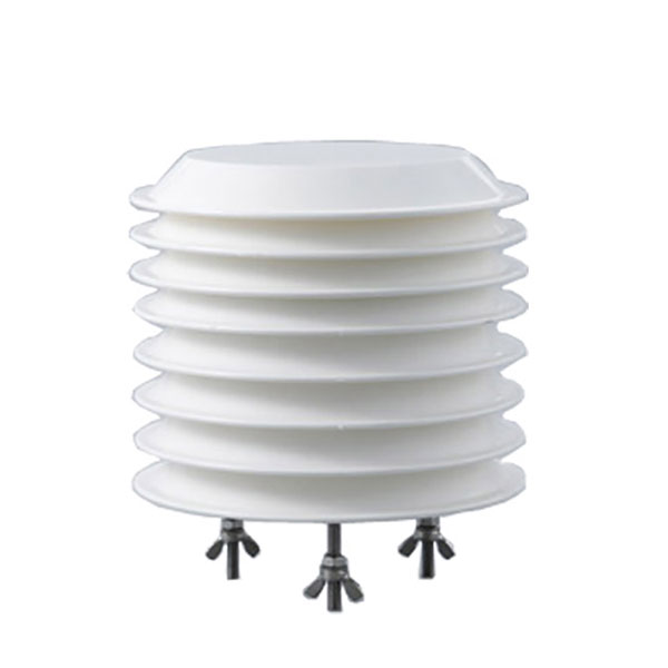 Combined air temperature and relative humidity sensor
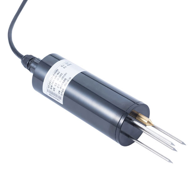 TDR Soil Moisture & Temperature Sensor for irrigation| RS485 |4-20mA| NBL-S-THR
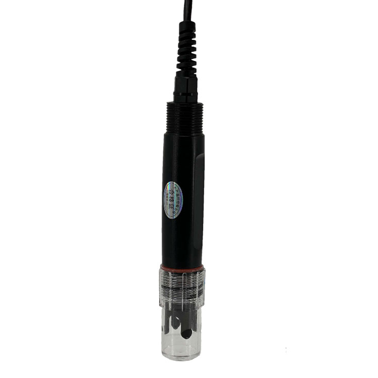 Soil pH sensor RS485 soil Testing instrument soil ph meter for agriculture |NBL-S-PH
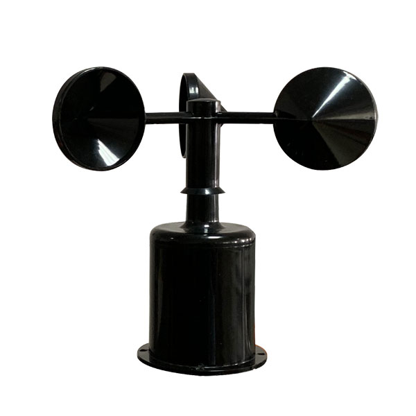 Wind Speed sensor Output Modbus/RS485/Analog/0-5V/4-20mA
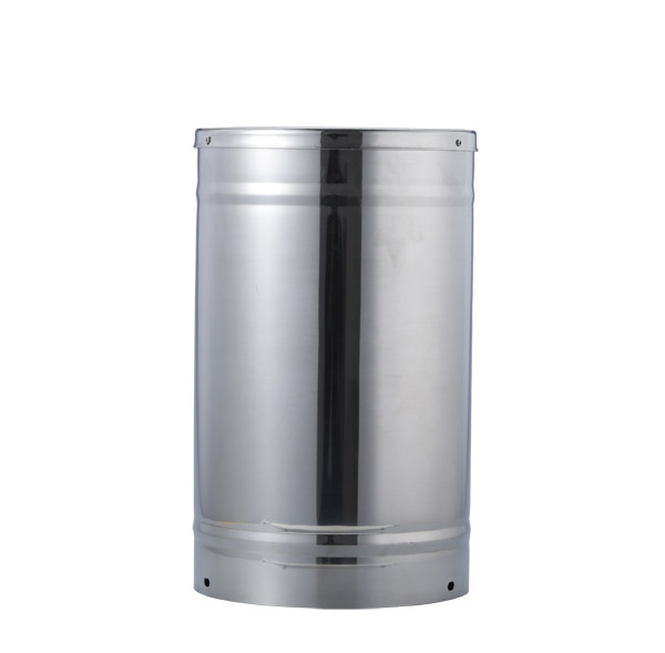 Tipping bucket rain gauge for weather monitoring auto rainfall sensor RS485/Outdoor/stainless steel
 Pyranometer Solar Radiation Sensor 4-20mA/RS485

Screenshot, WhatsApp to identify the QR code
WhatsApp number:+8615367865107
(Click on WhatsApp to copy and add friends)