

— Blogs —
—Products—
 Consumer hotline +8618073152920
 WhatsApp:+8615367865107
Address:Room 102, District D, Houhu Industrial Park, Yuelu District, Changsha City, Hunan Province, China
Product knowledge
Time:2026-09-09 13:00:00 Popularity:216
Quick Answer: Select a 3D ultrasonic anemometer when the project needs signed wind components along three axes, not merely more weather parameters. The useful deliverable is a correctly oriented, timestamped vector record at a suitable update rate. Confirm the component definitions, measurement uncertainty and logger behavior before ordering; three-axis geometry alone does not qualify an instrument for high-frequency turbulence or flux research.
Three-dimensional wind is justified when vertical velocity, turbulence or vector detail supports the project decision; many routine stations only need horizontal wind. A research team investigating upward flow near a building needs a different record from a site operator reviewing hourly wind direction.
Write the required result in measurable terms. Examples include the distribution of vertical velocity at a fixed point, a three-component comparison between two positions, or a synchronized fluctuation record for a defined analysis. Each requires different timing, uncertainty and installation information. A specification that says only "3D wind monitoring" leaves these decisions unresolved.
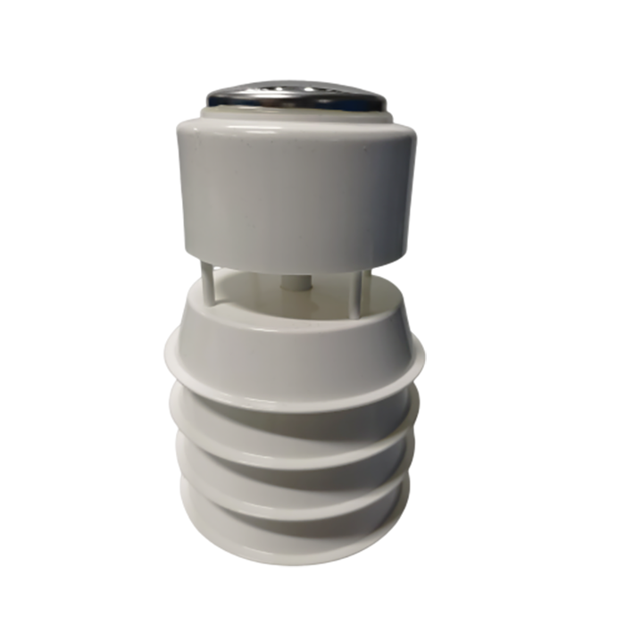
For routine weather networks, a compact multi-parameter station may be appropriate. Its parameter count does not establish three-dimensional wind measurement. Temperature, humidity, pressure and rainfall are separate weather quantities, not additional wind axes.
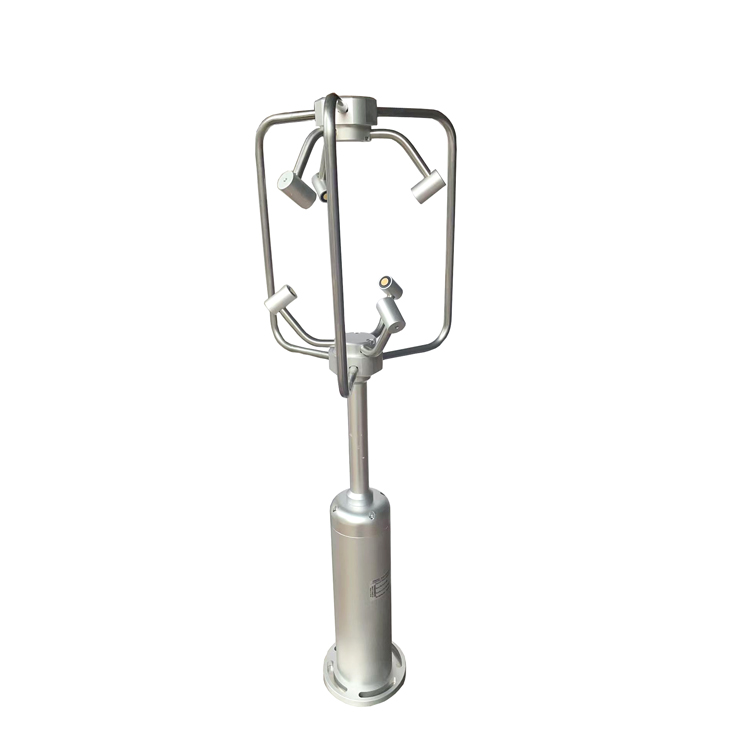
A three-axis instrument resolves velocity along its own X, Y and Z directions. These may be named U, V and W in the acquisition system, but the names do not prove that X points east or Z points upward after installation. The physical orientation and any coordinate conversion must be known.
For simultaneous orthogonal components, horizontal speed is sqrt(U squared + V squared), while three-dimensional resultant speed is sqrt(U squared + V squared + W squared). In an illustrative vector with U = 3 m/s, V = 4 m/s and W = 12 m/s, horizontal speed is 5 m/s and resultant speed is 13 m/s. Comparing those two outputs as if they were the same wind quantity would suggest a fault where none exists.
Check how the instrument calculates averaged outputs. The magnitude of an averaged vector is not generally the average of instantaneous magnitudes. If equal-duration samples have U = +5 and -5 m/s, with V and W zero, mean scalar speed is 5 m/s but the mean vector is zero. A logger must retain the statistic required by the application rather than label both results simply "wind speed."
| Application | Value of three-axis data | Selection limit |
|---|---|---|
| Airflow around buildings or bridges | Identifies vertical and lateral movement at a defined observation point. | One point does not describe the full structure or replace a qualified structural loading study. |
| Terrain and canopy research | Supports comparison of airflow components at selected heights or locations. | Exposure, coordinate orientation and timing must be comparable between instruments. |
| Ventilation investigations | Shows local flow direction where a horizontal-only result is insufficient. | Low-speed uncertainty and the instrument's physical effect on the flow can determine suitability. |
| Atmospheric turbulence or flux studies | Three velocity components may form part of the measurement system. | Requires verified bandwidth, synchronization, processing and suitable companion measurements. |
| Mobile platforms | Measures the local three-dimensional relative airflow. | Earth-referenced wind additionally needs platform orientation and motion data. |
For an urban airflow survey, distinguish representative background wind from the disturbed flow being investigated. A sheltered reading can be correct for the local study point but unsuitable as a reference for the whole site. Record both the objective and the obstacle geometry so another engineer can interpret the measurement later.
A 3D sensor also cannot automatically measure gas flux. Eddy-covariance work requires suitable velocity fluctuations and synchronized scalar measurements, together with method-specific corrections. Establish those capabilities for the complete system before presenting a three-axis weather instrument as a research solution.
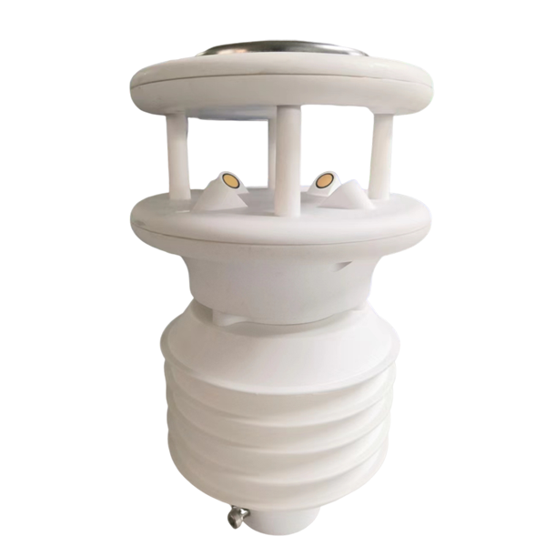
The NiuBoL NBL-W-3D-UWDS provides resultant speed, horizontal and vertical angles, and X/Y/Z wind components through an RS485 interface. Its acoustic transit-time measurement has no rotating cup or vane. That reduces mechanical servicing but does not eliminate inspection of the acoustic paths.
| Item | NBL-W-3D-UWDS | What to verify for the project |
|---|---|---|
| Resultant speed range | 0-60 m/s; resolution 0.01 m/s | Do not treat the display increment as speed accuracy. |
| Axis components | X/Y/Z: -60 to 60 m/s; resolution 0.01 m/s | Signed decoding and the physical positive direction of each axis. |
| Angles | Horizontal 0-359 degrees; vertical -90 to 90 degrees; accuracy +/-3 degrees; resolution 1 degree | Direction convention and behavior near calm conditions. |
| Supply and power | 9-24 V DC; average consumption 2 W | Peak demand and any additional heating or communication loads. |
| Communication | RS485 Modbus RTU; 9600 bit/s | Actual independent update rate, serial settings and receiving-system capacity. |
| Operating temperature | -40 to 80 degrees C | Exposure of the complete assembly, connectors and logger. |
| Wind sensor protection | IP65 | Separate requirements for icing, deposits and corrosion. |
For a low-speed or vertical-fluctuation study, request the applicable component accuracy and calibration results at the required velocities. A wide measuring range is not proof that a small vertical signal can be resolved with the needed uncertainty. Confirm cable construction and connector requirements for the site rather than assuming they follow from the digital protocol.
Measurement rate is how often the sensor produces a new observation. Polling rate is how often the host requests a value. Recording rate is how often the logger saves a record. These rates can differ. Polling an unchanged register repeatedly creates more records, not more independent wind measurements.
At 9600 bit/s with an illustrative 8N1 serial format, each byte occupies ten bits on the wire. An eight-byte request followed by a seventeen-byte response requires about 26 ms of transmission time alone. Device processing, mandatory frame separation, other bus traffic and retries increase that time. This calculation is a communication budget, not a claim that the anemometer measures or delivers new vectors at a particular frequency.
Ask for a time-series export at the intended rate, including timestamps and status, and test it with the proposed logger. Examine repeated values, gaps and timestamp spacing. Quantized steady flow can legitimately produce repeated numbers, so use a suitable controlled change when checking whether samples are independent.
Store all components from the same measurement cycle together. Sequentially reading different channels at different times can distort a rapidly changing vector. Where the device supports a multi-register read, verify its behavior and output timing rather than assuming that a single transaction necessarily proves simultaneous internal sampling.
Before field installation, identify the reference mark and each axis direction. Test the receiving system with known signed component values or an appropriate device simulation. Confirm that a negative value stays negative after storage, export and visualization. A checksum validates message integrity, not the interpretation of its data.
In controlled airflow, reorient the test assembly as permitted by the test setup and check that the expected component changes sign or magnitude. Use this to verify channel identity and conventions, not to claim a wind-speed calibration. Do not substitute hand blowing for a controlled reference test.
After mounting, check level and orientation again under the final fastener load. Keep brackets and cable loops away from the acoustic paths. A mast wake can produce direction-dependent differences that no electronic offset will correct. For detailed mounting practice, use the ultrasonic wind sensor installation guide.
Retain raw components as well as derived speed, angle or summary statistics. Record which coordinate transformation and averaging method produced each derived channel. If a processing method changes, the original data should remain available for recalculation rather than being replaced by the new result.
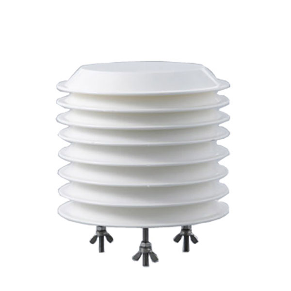
Where temperature or humidity is part of the investigation, acquire those channels with their own exposure requirements. A nearby shielded atmospheric sensor adds environmental context, but its response and timestamp behavior differ from the wind measurement. Shared logger storage does not make every sensing element synchronous.
Plan inspection around the actual environment. Deposits and damaged transducers can alter acoustic performance, while ice can obstruct a path. Avoid scraping transducers or adding unapproved coatings. After cleaning or repositioning, check for a step in the component record and annotate the maintenance time.
For a quotation, provide the variables and statistics needed, expected minimum velocities, target uncertainty, required record rate, mounting geometry and available logger interface. Request a sample data export for integration testing. The choice should be based on whether the instrument can produce the required record, not on a general promise of research suitability.
Only when the vertical component is zero or negligible for the required comparison. Resultant speed includes all three orthogonal components. Label the output explicitly and use the same definition when comparing instruments or calculating project statistics.
No. Polling cannot increase the instrument's measurement bandwidth or recover fluctuations removed by internal averaging. Verify independent update rate, filtering and time synchronization against the analysis requirements before selecting the instrument.
Check the receiver's signed-value interpretation and scaling. The data may be arriving correctly but being decoded as unsigned. Confirm the encoding for the installed firmware and test negative values through the complete storage and export path.
Not merely because it measures many parameters. The channel list must explicitly include the required three signed velocity components. A station with horizontal wind, temperature, humidity and other weather channels may still provide only two-dimensional wind information.
It can measure relative airflow if the installation suits the instrument. Earth-referenced wind requires compatible platform motion and orientation measurements with aligned timestamps. The third axis does not automatically remove vehicle motion from the result.
Provide the exact output variables, applicable uncertainty information, firmware-specific data format and a test export at the proposed recording rate. Confirm mounting and synchronization requirements with the end user. Where the evidence does not support the requested analysis, propose a different measurement arrangement rather than relying on the product category name.
A 3D ultrasonic anemometer is useful when the project can use its three-component record. Define the vector quantities and statistics, verify the actual data rate, and test coordinates and signed decoding before deployment. Those checks determine whether the delivered data will answer the research or engineering question.
Prev:Abnormal Rainfall Data: Diagnosis for Weather and Hydrology Stations
Next:Forest Fire Weather Station: Parameters, Installation and Alarm Design
Related recommendations
Sensors & Weather Stations Catalog
 Agriculture Sensors and Weather Stations Catalog-NiuBoL.pdf
Weather Stations Catalog-NiuBoL.pdf
Agriculture Sensors Catalog-NiuBoL.pdf
Water Quality Sensor Catalog-NiuBoL.pdf
Related products
Combined air temperature and relative humidity sensor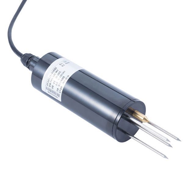 TDR Soil Moisture & Temperature Sensor for irrigation| RS485 |4-20mA| NBL-S-THR
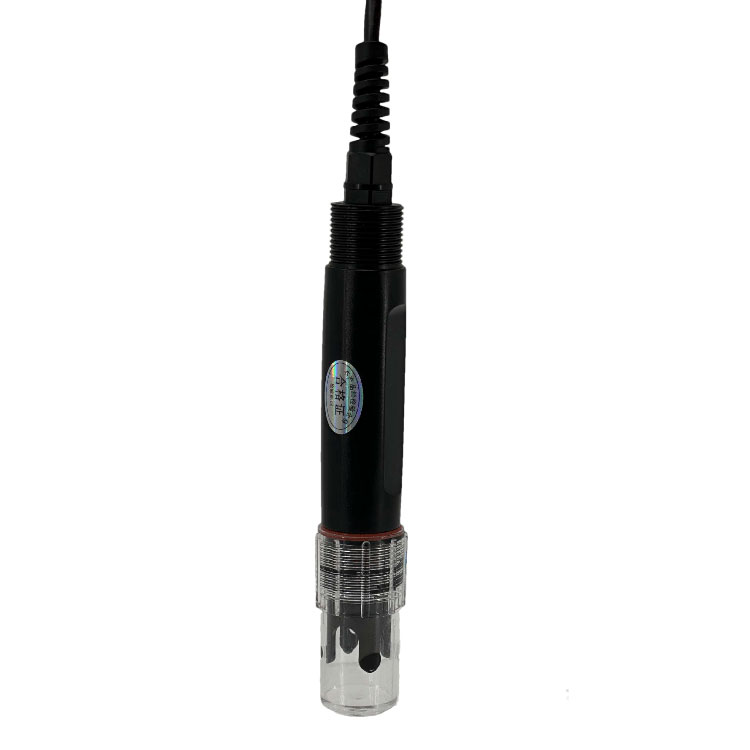 Soil pH sensor RS485 soil Testing instrument soil ph meter for agriculture |NBL-S-PH
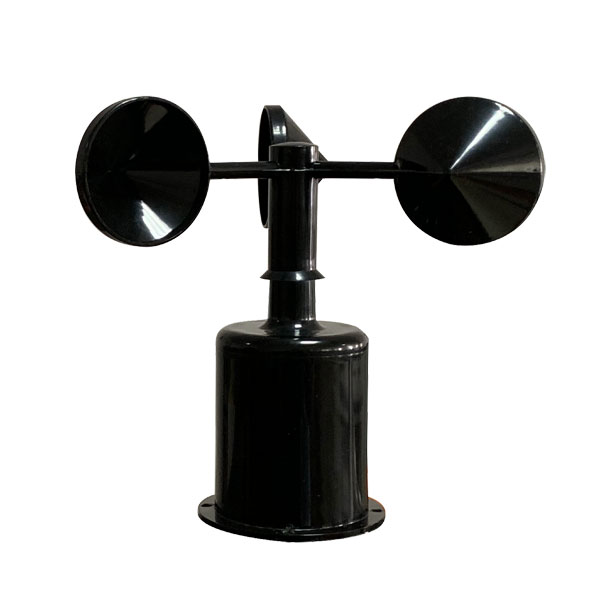 Wind Speed sensor Output Modbus/RS485/Analog/0-5V/4-20mA
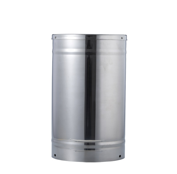 Tipping bucket rain gauge for weather monitoring auto rainfall sensor RS485/Outdoor/stainless steel
 Pyranometer Solar Radiation Sensor 4-20mA/RS485

Screenshot, WhatsApp to identify the QR code
WhatsApp number:+8615367865107
(Click on WhatsApp to copy and add friends)