





— Blogs —
—Products—
 Consumer hotline +8618073152920
WhatsApp:+8615367865107
Address:Room 102, District D, Houhu Industrial Park, Yuelu District, Changsha City, Hunan Province, China
Product knowledge
Time:2026-09-25 11:00:00 Popularity:223
Quick Answer: Drinking water monitoring points should follow the treatment and distribution decisions they support. A plant outlet, a network storage outlet and a secondary-supply tank outlet represent different water histories. Define the water source at each point, sample delay, required measurement and operator response before selecting probes or fixing the sampling cabinet.
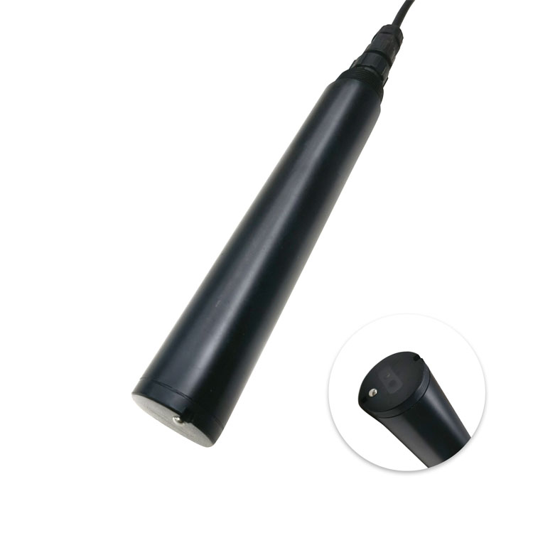
An immersed turbidity probe and a low-range flow-through turbidimeter are different installation choices. Select the method and low-end performance required at the point; a generic online probe is not automatically suitable for every treated-water measurement.
| Location | Question the point should answer | Placement detail that matters |
|---|---|---|
| Individual filter outlet | Is the selected filter's output changing? | Keep the point attributable to that filter before downstream blending masks the change |
| Finished-water plant outlet | What water is entering distribution after the intended treatment stages? | Identify the position relative to final dosing, mixing, storage and the defined contact process |
| Distribution storage outlet | How does water leaving storage differ from incoming water? | Confirm that the sample follows outflow rather than stagnant water in an isolated connection |
| Selected network location | How does a supply zone or hydraulically distant area behave? | Use network flow and water-age information, not distance alone, to justify the point |
| Secondary-supply tank or booster system | What changes across storage and local pumping? | Distinguish incoming water, tank outlet and downstream delivery; record pump and tank operating states |
Do not label all these points simply "drinking water." A plant-outlet trend is a useful baseline, but it does not represent every network branch. A tank-outlet value also does not establish the condition of an intermittently used terminal line.
The EPA online water quality monitoring resources distinguish source-water and distribution-system monitoring. For an actual installation, combine that monitoring purpose with the utility's hydraulic information and required sampling program. Online observations support operations and investigation; they do not replace every microbiological or chemical analysis.
Turbidity at a filter outlet addresses a different question from disinfectant residual near a storage outlet. pH can help interpret chlorine response and treatment changes. Conductivity may reveal mixing or source changes, but it does not identify a specific contaminant. Choose channels for the decisions at that point instead of installing an identical set everywhere.
For chlorine, state whether the objective is free residual chlorine, total residual chlorine or another defined species. A chloraminated system cannot be represented by a free-chlorine channel merely because both values use mg/L. Define the instrument and comparison method together.
A cabinet beside a convenient power source may be far from the actual water contact point. Before accepting its response time, calculate the sample-line volume and divide it by the flow reaching the instrument. Then add flow-cell residence, sensor response and processing. Logging more frequently does not remove this delay.
For illustration, a 20 m line with a 6 mm internal diameter contains approximately 0.565 L. At 0.25 L/min, nominal travel time is about 2.3 minutes before adding fittings, a flow cell or measurement response. These are example dimensions, not a specified installation. A pressure regulator or partially closed valve can increase the actual delay.
Long travel can matter for disinfectant residual because the sample may change before measurement. Use suitable materials, avoid stagnant sections and compare with a fresh sample near the relevant process point. A cabinet reading after a lengthy shutdown should not be treated as current network water until sample delivery has been restored and checked.
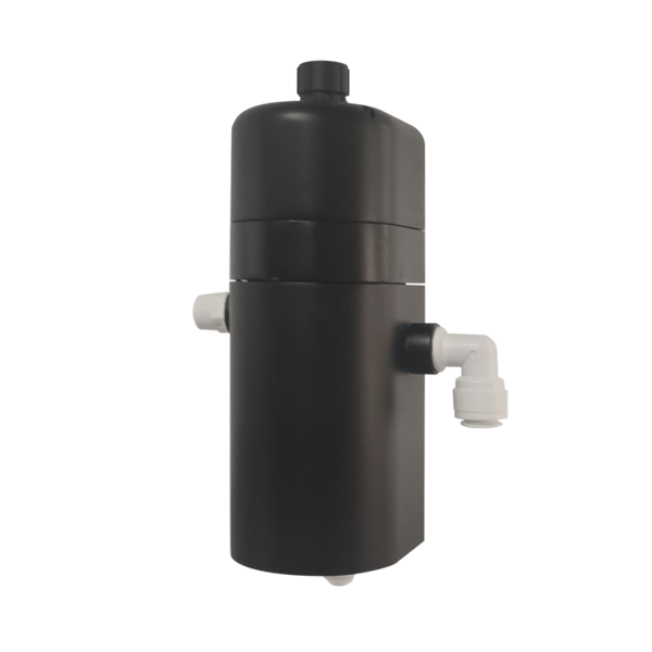
The NiuBoL NBL-WQ-TSA-4 integrates a flow-through cell and a 90-degree scattered-light sensor. It is a different format from an immersed multi-parameter probe. Its low-range specification is useful for comparison, but suitability still depends on the required method and performance at the actual reporting level.
| Item | NBL-WQ-TSA-4 configuration | Installation consequence |
|---|---|---|
| Range and resolution | 0-10.000 NTU; 0.001 NTU | Do not mistake display resolution for verified low-level accuracy or detection performance |
| Accuracy specification | +/-5% or +/-0.02 NTU, whichever is greater | Confirm the percentage basis and performance needed at the site's decision level |
| Sample flow | Recommended below 300 mL/min | Provide stable controlled flow and an unobstructed outlet |
| Pressure | No higher than 0.2 MPa | Review the maximum pressure and the complete sample assembly, not only normal flow |
| Power | 12-24 V DC; 0.2 W at 12 V | Include controller and auxiliary loads separately |
| Interface | RS485 Modbus RTU; optional 4-20 mA | Specify the actual ordered output |
| Housing and protection | Composite housing; IP65; wall mounting | Do not submerge the instrument or treat it as an IP68 immersed probe |
An NTU label does not establish approval for every reporting method. Likewise, a process monitoring application and a compliance reporting application may have different requirements. Confirm the applicable method and documented performance before specifying a device for a regulated measurement point.
The NBL-WQ-CL chlorine probe's matching flow-cell configuration uses 30-60 L/h, equivalent to 0.5-1.0 L/min. That differs from the TSA-4 recommendation of less than 0.3 L/min. Simply putting the two in series at one flow setting does not satisfy both stated conditions.
Where both channels are needed, consider separately regulated sample branches with their own checked flow and suitable outlets. Review whether an upstream instrument changes the downstream sample. A shared take-off can be practical, but each measuring branch must receive representative water under its own required conditions.
Provide isolation and access appropriate to the installation so that a sensor can be checked without uncontrolled water release or contaminating the supply. Review wetted materials, backflow protection and sample disposal against the utility's requirements. Do not assume that a monitoring outlet may be returned to the potable network.
Keep a suitable comparison-sampling location and clearly label which water it represents. A bottle taken from another tap may differ because of local stagnation, pipe material or collection timing. For low-level turbidity comparisons, bottle cleanliness, handling and bubbles also matter.
An upstream strainer or sample-conditioning step can alter particle measurements. Where protection is necessary, evaluate its effect on the required result rather than silently filtering the sample before a turbidity channel. Record any treatment applied to the sample path.
Alarm logic belongs to the operational plan. A low residual, a failed sample flow and a communication timeout are different conditions and may require different responses. The sensor's RS485 Modbus RTU connection does not implement the required dosing or operator escalation by itself.
For a NiuBoL monitoring-point quotation, send a process or network sketch, the intended take-off location and the required result at each point. Include sample-line length and internal diameter, available pressure, branch-flow needs and the required host interface. This makes it possible to review a workable sample arrangement rather than only price individual probes.
No. It describes water entering distribution at that point. Storage, mixing, residence time and local operation can change conditions downstream. Select additional monitoring points using the network's behavior and the operating questions to be answered.
Not necessarily. A filter-outlet turbidity point, a disinfectant-residual point and a source-mixing investigation can need different channels and sampling arrangements. Standardize components where useful without assuming the measurement task is identical.
Not at a single unreviewed flow setting. The stated flow conditions differ: TSA-4 recommends below 0.3 L/min, while the specified CL flow cell uses 0.5-1.0 L/min. Evaluate separate regulated branches and verify the sample condition for each channel.
No. The measured water first has to reach the sensor. Calculate sample volume divided by actual flow, then add instrument and processing response. Check this total against the event duration and response time required by the project.
The TSA-4 configuration discussed here is wall-mounted and IP65, with an integrated sample cell. It is not an immersed IP68 probe. Use a suitable sample path or select an instrument intended for immersion.
No. Online instruments observe installed parameters by their specified methods. Drinking-water assessment also requires the applicable sampling, analytical and operational requirements, including tests that the station does not perform.
Identify each monitoring location, required parameter and reporting method, sample pressure and flow, line dimensions, available outlet and maintenance access. Include the controller interface and any required sample-loss alarm so that missing installation items are visible in the quotation.
Useful drinking water monitoring points represent specific stages of the water's route. Keep the sample representative, quantify its travel delay and match each branch to the instrument's hydraulic requirements. NiuBoL probes and flow-through instruments can then be selected for defined measurements without treating one station as evidence for the entire supply network.
Prev:Cabinet-Type Online Water Quality Monitoring Station
Next:Chlorine Monitoring During Disinfectant Changeover: Free or Total?
Related recommendations
Sensors & Weather Stations Catalog
 Agriculture Sensors and Weather Stations Catalog-NiuBoL.pdf
Weather Stations Catalog-NiuBoL.pdf
Agriculture Sensors Catalog-NiuBoL.pdf
Water Quality Sensor Catalog-NiuBoL.pdf
Related products
 Combined air temperature and relative humidity sensor
 TDR Soil Moisture & Temperature Sensor for irrigation| RS485 |4-20mA| NBL-S-THR
 Soil pH sensor RS485 soil Testing instrument soil ph meter for agriculture |NBL-S-PH
 Wind Speed sensor Output Modbus/RS485/Analog/0-5V/4-20mA
 Tipping bucket rain gauge for weather monitoring auto rainfall sensor RS485/Outdoor/stainless steel
 Pyranometer Solar Radiation Sensor 4-20mA/RS485


Screenshot, WhatsApp to identify the QR code
WhatsApp number:+8615367865107
(Click on WhatsApp to copy and add friends)

