

— Blogs —
—Products—
 Consumer hotline +8618073152920
WhatsApp:+8615367865107
Address:Room 102, District D, Houhu Industrial Park, Yuelu District, Changsha City, Hunan Province, China
Product knowledge
Time:2022-09-11 16:46:07 Popularity:1865
Quick Answer: Agricultural IoT connects soil and weather measurements to farm records, irrigation scheduling and, where a controller is installed, field equipment. For irrigation, the useful chain is a root-zone reading, a decision for one irrigation zone, a measured water application and a check of the soil response. A dashboard alone cannot confirm that water reached the crop.
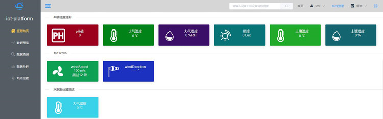
A grower may ask whether a block needs water. An irrigation contractor needs to establish something more specific: which valve serves that block, whether the soil sensor represents its roots, how much water the valve delivered and whether drainage occurred below the intended root zone. These are different measurements. Combining them makes an agricultural IoT system useful for daily operation rather than simply remote observation.
For irrigation, define which zone, crop and root depth the measurement represents. For greenhouse control, define acceptable temperature and humidity bands, actuator capacity and safety limits. A temperature alarm or dry-soil reading should identify the affected zone and the action available to the operator, not just show a red tile on a screen.
Three practical starting points are a soil-monitoring installation for irrigation advice, a weather station supplying local scheduling inputs, and a greenhouse installation that compares indoor conditions with equipment operation. Start with the task that currently causes uncertainty. A small installation covering a representative block is easier to evaluate than a large sensor network without a defined operating purpose.
| Farm decision | Measurements to combine | What the readings cannot establish alone |
|---|---|---|
| When to irrigate a field block | Root-zone soil moisture; recent rainfall; irrigation history | A single probe does not represent different soil textures or separate valve zones. |
| Whether an irrigation event worked | Valve command; measured flow; soil response at selected depths | An open command does not prove that a valve opened or that emitters delivered water. |
| How weather affects demand | Air temperature, relative humidity, wind and solar radiation; rainfall for the water balance | Weather-based demand is not a direct measurement of water stored around the roots. |
| Whether greenhouse ventilation responds | Indoor temperature and humidity; outdoor reference; fan or vent feedback | A controller output does not prove airflow or vent movement. |
| Whether salinity needs investigation | EC trend with temperature, moisture and irrigation-water context | EC does not identify individual nutrients or replace an appropriate laboratory analysis. |
Soil moisture should be interpreted with soil texture, root depth and irrigation layout. Rainfall and weather data can adjust planned irrigation, but a station reading should not be applied across unlike zones without verification. Fertigation control also needs flow, pressure and dosing safeguards; EC trends do not identify individual nutrients.
NiuBoL offers the NBL-S-TM soil temperature and moisture sensor and the NBL-S-TMC soil temperature, moisture and EC sensor. The additional EC channel is useful when salinity trends matter; it is not automatically necessary for a simple irrigation-advisory point. Specify the electrical output variant when ordering. An RS485 connection requires a compatible protocol implementation, not merely a matching terminal label.
Keep volumetric water content separate from relative humidity. A soil-water reading expressed as a percentage by volume describes water per bulk soil volume; greenhouse relative humidity describes water vapour in air relative to saturation. Label these channels differently in the platform. A common percentage symbol is not a reason to share an alarm threshold or conversion.
Group the site by soil texture, crop, rooting depth, irrigation method and hydraulic behaviour. Select a representative position in each materially different group. Avoid an unusually wet low point, a leaking emitter or a field edge unless that condition is specifically being investigated. A probe beside the easiest cable route may give a reliable reading of the wrong location.
For drip irrigation, record the probe's distance from the emitter and the row as well as its depth. Install with close soil contact and avoid an air gap around the sensing elements. Two nearby probes at different depths answer different questions: the shallower point can show wetting in the active root zone, while a deeper point can help identify downward movement. Actual depths must follow crop roots and the local soil profile, not a universal centimetre value.
Before enabling automatic irrigation, observe several irrigation and drying cycles. Compare the electronic trend with a field inspection and the known soil condition. Establish an appropriate refill threshold for that block with the agronomist or farm manager. Copying a threshold from a sandy block to a clay block can change the amount of plant-available water represented by the same percentage reading.
As an illustrative calculation, assume a uniformly wetted soil layer 0.30 m deep rises from 0.20 to 0.24 m3/m3. The estimated storage increase is (0.24 - 0.20) x 0.30 x 1,000 = 12 mm. Across a uniformly wetted hectare, 12 mm corresponds to 120 m3. These figures describe an assumed water-storage change, not a NiuBoL field result or a recommended irrigation dose.
Now compare that estimate with a flow-meter total for the event. A large difference warrants investigation of wetting coverage, drainage, runoff, probe placement or the assumed soil depth. Under drip irrigation the wetted fraction may be much smaller than the entire block, so extrapolating one probe to a hectare without that correction can substantially misstate stored water.
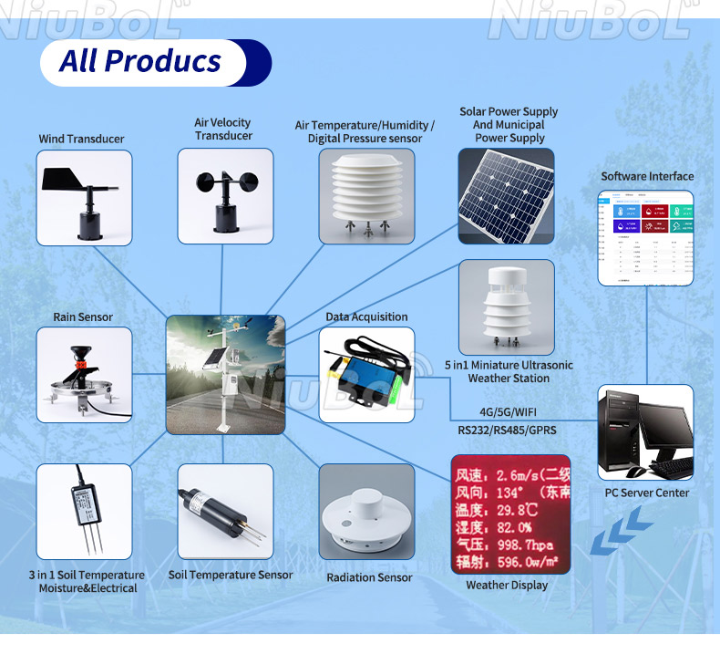
The field chain usually runs from sensors to a data logger or RTU, then through a communications link to the farm platform. Irrigation control adds a controller, valve or pump interface and feedback devices. A serial-to-cellular communications unit can transmit readings without having the outputs, interlocks or local logic required to operate a pump. Select those functions explicitly.
For RS485 Modbus RTU integration, obtain the register map for each ordered sensor. Check device address, baud rate, parity, function code, register offset, signed values, decimal scaling and invalid-reading behaviour. Give every device on one bus a unique address. A gateway that receives a serial response still needs the correct map to display the physical value and unit.
Separate pulse inputs from serial channels in the equipment schedule. A pulse-output rain gauge needs a counter and a known rainfall-per-pulse factor. An RS485 rain gauge needs a protocol driver. Likewise, a 4-20 mA pressure transmitter requires an appropriate analogue input and scale; an RS485-only logger cannot read its current loop without an additional interface.
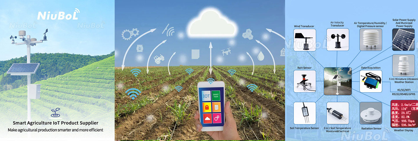
NiuBoL weather-station data loggers and RTU equipment provide possible acquisition routes. Match the selected hardware and firmware to the channel list, local storage requirement and communications arrangement. Confirm buffer capacity and automatic backfill where historical completeness matters; do not assume every router or data collector supplies both.
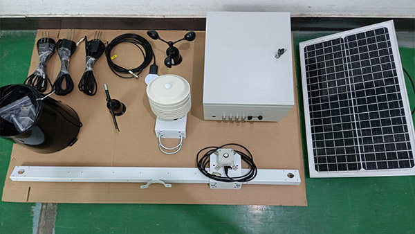
A weather station measures conditions affecting water demand. A soil probe measures a local soil condition. They complement each other: weather can help plan the next irrigation, while the soil trend shows whether the root zone actually became wetter and how it dried afterwards. Rainfall also needs interpretation: water measured in the collector is not necessarily water retained by the crop after interception, runoff and drainage.
The FAO-56 crop evapotranspiration method distinguishes reference evapotranspiration from crop evapotranspiration and uses meteorological inputs including temperature, humidity, wind and radiation. A platform showing those channels does not necessarily calculate a valid irrigation schedule. Check the calculation method, sensor exposure, time interval and crop-stage assumptions before using its result to set valve run time.
In orchards, an exposed weather station and probes beneath the wetted tree row serve different purposes. In a greenhouse, outdoor rainfall may have little direct effect on covered soil but outside radiation and temperature can still affect demand. Treat those as different operating cases rather than assigning the same rule to every site.
Choose a supervised event with a known zone and an operator present. First compare the sensor readings at the logger and platform, including timestamps and units. Open the valve through the intended control route, then verify actual flow and pressure. Watch the root-zone trend during and after the event; the response may lag the command because water must travel through pipes and soil.
If flow remains near zero after an open command, investigate the valve, pump, supply and meter before changing a soil threshold. If flow is normal but the probe remains unchanged, inspect emitter coverage and probe location. If a deeper probe rises repeatedly after long runs while the active root zone is already wet, review irrigation duration and drainage rather than treating the deeper rise as a communications fault.
Test stale-data handling separately from a low-moisture alarm. Disconnect a sensor and confirm that the last valid value is marked as stale, not displayed as a fresh measurement. Irrigation logic must have a defined response to that condition, such as inhibiting sensor-triggered starts and notifying the operator. Independent limits on run time and safe pump operation remain necessary even with a working internet connection.
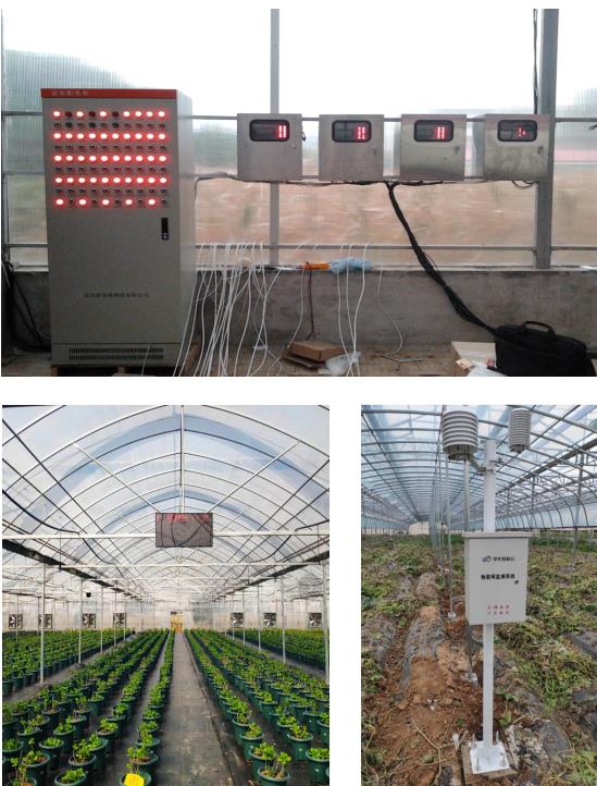
Indoor sensors should be positioned away from heaters, wet walls and direct radiation. Outdoor reference measurements help distinguish weather effects from equipment faults. The controller may coordinate ventilation, shading, heating and irrigation, but conflicting actions need priorities and dead bands.
Separate monitoring from control in a quotation. List sensor locations, valve zones, existing pump controls, required feedback, cable distances and the available power supply. Then identify whether NiuBoL is supplying sensors and acquisition equipment or whether the project also requires control-panel integration and platform development. This avoids comparing a monitoring-only price with a complete irrigation-control installation.
Seasonal set-point changes should be versioned. Operators need to know who changed a threshold, when it changed and whether the old value can be restored. Keep a local means of operating essential equipment during network or platform outages. Remote access should not remove the farm's ability to stop a pump or isolate a faulty valve.
Use the number of materially different management zones, not acreage alone. Soil texture, crop, rooting depth and irrigation hydraulics determine whether one point represents a block. Begin with representative zones and compare their behaviour before extending coverage; add depths where downward wetting or drainage needs investigation.
Yes, with suitable control hardware and commissioned logic. Use validated zone thresholds, stale-data detection, maximum run time and the necessary pump protections. A sensor and cloud dashboard without valve outputs or feedback remain a monitoring system.
No. It reduces cabling but adds coverage, antenna and battery considerations. Test the actual installation with seasonal canopy and enclosure positions considered. Wired RS485 can suit nearby powered points; cellular backhaul can carry data from a logger, but does not eliminate field-side wiring or power requirements.
No. Weather inputs estimate atmospheric demand and record local rainfall, while soil probes reveal conditions at selected positions and depths. Soil type, irrigation distribution and drainage can produce different root-zone conditions under the same weather.
Check depth, emitter distance, soil contact and irrigation coverage before recalibration. A difference can be physically real. Compare units and scaling as well, then observe another supervised event to distinguish placement effects from a faulty channel.
Provide the crop and zone layout, proposed measurements and depths, preferred output, logger or PLC details, power availability, cable distances and communications coverage. Identify existing valves, pumps and feedback instruments if control is required. Ask for separately itemised sensors, acquisition, communications, power and integration work.
Agricultural IoT becomes useful when a measurement can be traced to an irrigation zone and checked against actual equipment operation and soil response. NiuBoL soil sensors, weather instruments and data-acquisition equipment can form that measurement chain. Choose the channels and interfaces around the farm decision, then prove the result in a supervised operating cycle before extending automation.
Prev:Agrometeorological monitoring to ensure safe crop growth
Next:IOT pest detection and warning light to build a pest ecological monitoring and early warning system
Related recommendations
Sensors & Weather Stations Catalog
 Agriculture Sensors and Weather Stations Catalog-NiuBoL.pdf
Weather Stations Catalog-NiuBoL.pdf
Agriculture Sensors Catalog-NiuBoL.pdf
Water Quality Sensor Catalog-NiuBoL.pdf
Related products
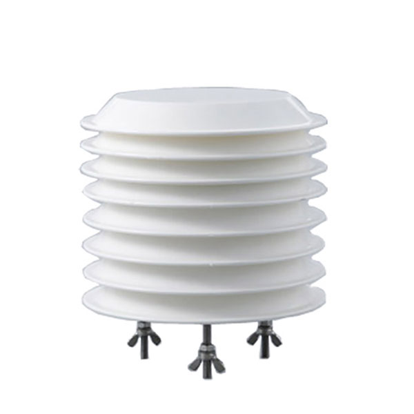 Combined air temperature and relative humidity sensor
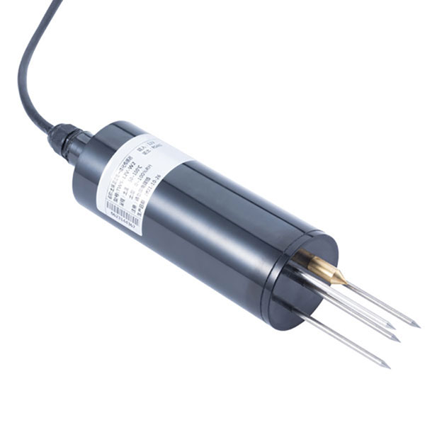 TDR Soil Moisture & Temperature Sensor for irrigation| RS485 |4-20mA| NBL-S-THR
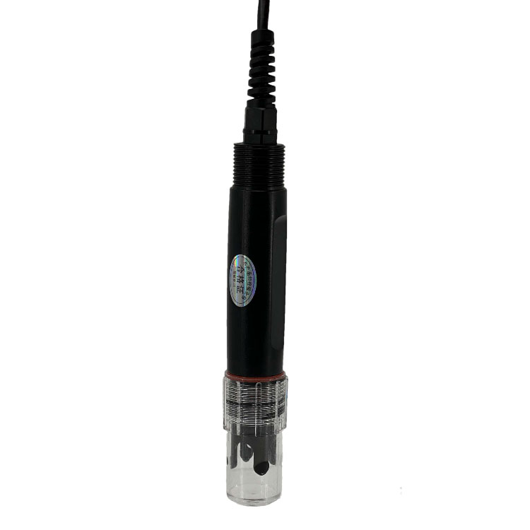 Soil pH sensor RS485 soil Testing instrument soil ph meter for agriculture |NBL-S-PH
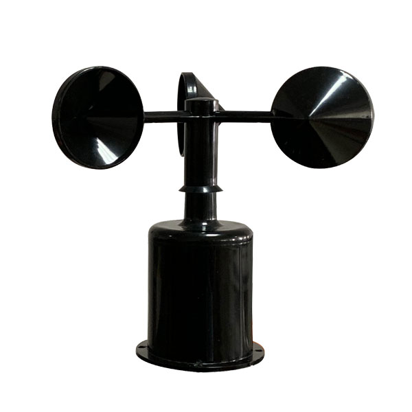 Wind Speed sensor Output Modbus/RS485/Analog/0-5V/4-20mA
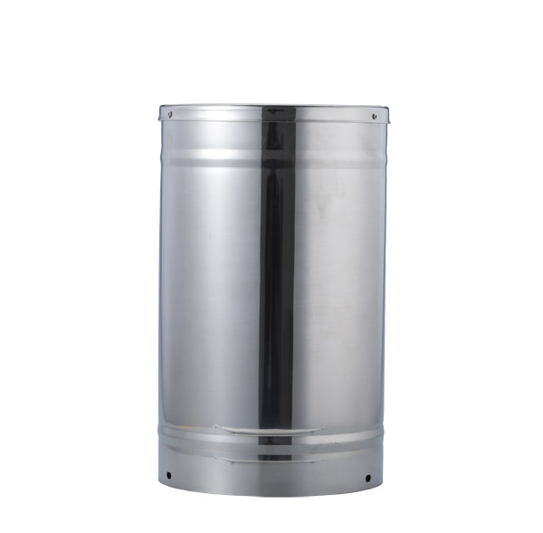 Tipping bucket rain gauge for weather monitoring auto rainfall sensor RS485/Outdoor/stainless steel
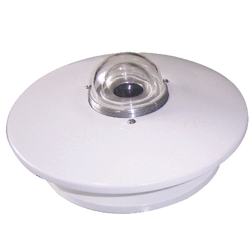 Pyranometer Solar Radiation Sensor 4-20mA/RS485


Screenshot, WhatsApp to identify the QR code
WhatsApp number:+8615367865107
(Click on WhatsApp to copy and add friends)